
US $260
| Condition: |
New: A brand-new, unused, unopened, undamaged item in its original packaging (where packaging is
applicable). Packaging should be the same as what is found in a retail store, unless the item is handmade or was packaged by the manufacturer in non-retail packaging, such as an unprinted box or plastic bag. See the seller's listing for full details.
...
|
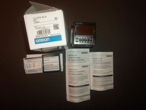
Brand | OMRON |
| Model | H7CX-AU-N |
Directions
Similar products from Digital & Hand Counters
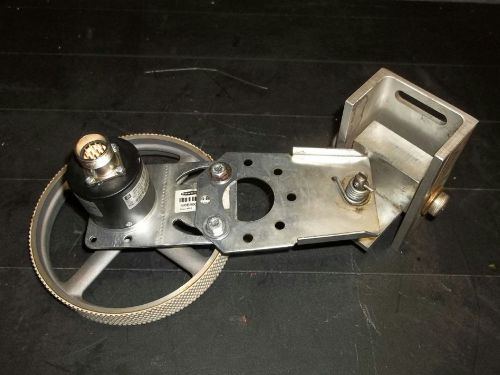
PEPPERL FUCHS INCREMENTAL ROTARY ENCODER RVI50N-098BAAA3TN-01000, 121080

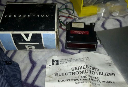
VEEDER-ROOT 799536-001 SERIES 7995 ELECTRONIC TOTALIZER 115 AND 230 VAC NEW $89
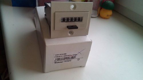
KUBLER Brand Mechanical Counter,F1B16.01, 230VAC,New!
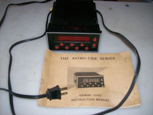
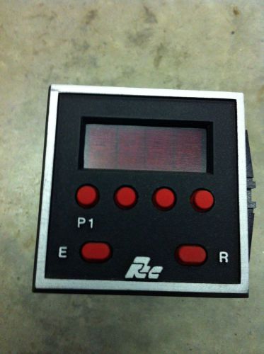
RED LION CONTROLS GEM 1 COUNTER
Lot of 2 Red Lion CUB20000 CUB2 Digital Counters - Need Batteries
Red Lion CUB20000 CUB2 Digital Counter - Needs Battery
Red Lion CUB2XP00 CUBII-XP Digital Counter - Needs Battery
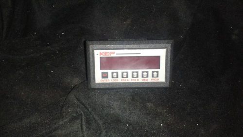
KEP ELECTRONIC COUNTER MODEL MR2A3
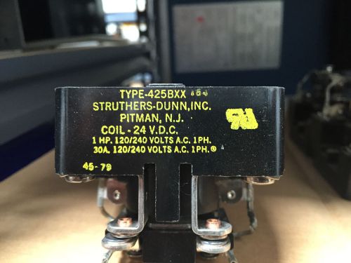
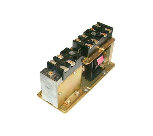
STRUTHERS-DUNN 425BXX RELAY COIL 24v 60Hz 30amp 120 240vac NEW
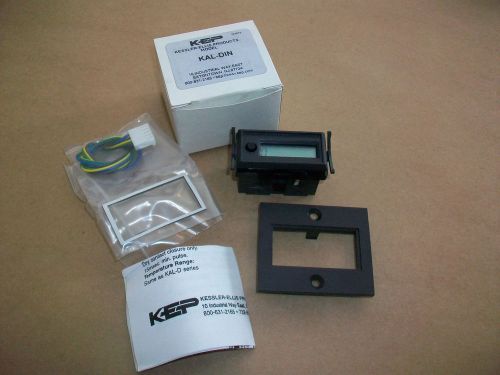
Kessler Ellis KEP 8 digit Counter KAL-DIN NEW IN BOX
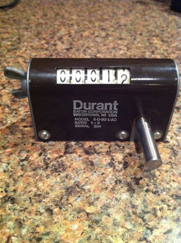
DURANT 6-Y-41322-406-MEQU COUNTER 120 VAC 3.5 W
RED LION LIBC1E00 DIGITAL COUNTER
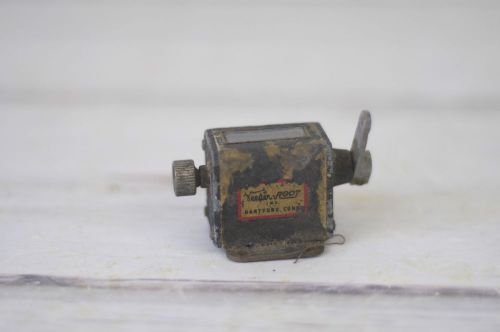
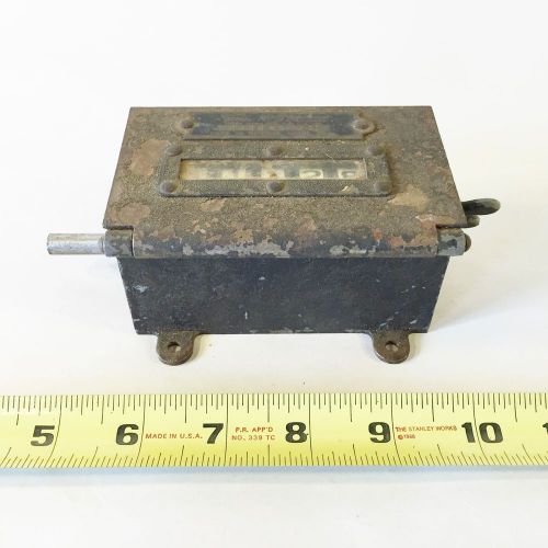
Vintage Veeder-Root Small 5 Digit Reset Counter 1948
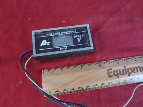
Red Lion DT500000 DITAK V Electronic Rate Indicator Counter---SEE PICS BELOW
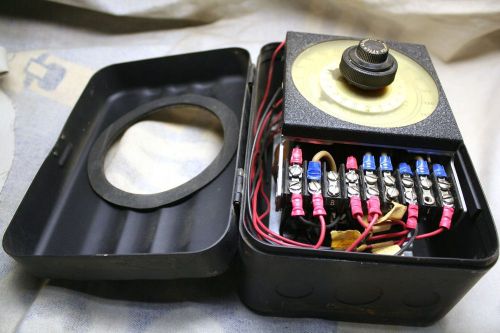
Eagle HZ40A6 0-400 Counts Counter/Switcher 115V15A In Case Wired Kodak 400 Multi

OMRON Counter H7CN-XHN H7CNXHN 100-240VAC new in box free ship
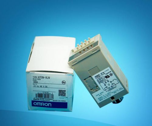
OMRON Counter H7CN-XLN H7CNXLN 12-48VDC new in box free ship
People who viewed this item also vieved
NEW ATC 305E 004 A 10 XK GP mechanical Timer 305E-A93304-02 15 seconds No Reserv
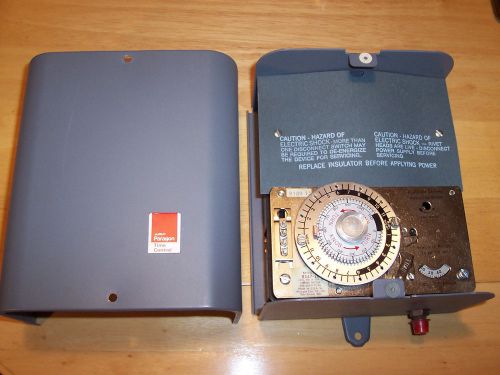
AMF Paragon Time Control Frost O Matic 8247-20
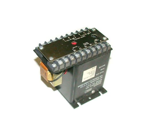
ISSC KANSON ELECTROVICS SOLID STATE TIMER MODEL 1013UL-1-K-1-BSP29
ALLEN BRADLEY TIME DELAY RELAY 110/120 VAC MODEL 849-ZOD337
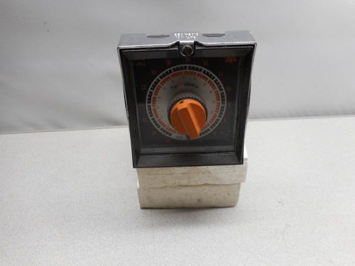
EAGLE SIGNAL CONTROL HG105A6-EIGNAL SIGNAL-DANAHER
ATC 342A200Q10PX FLIP-FLOP REPEAT CYCLE TIMER 120VAC 50/60HZ NEW IN PKG
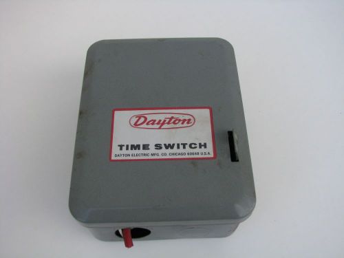
Dayton Timer Time Switch Model 2EO21 Single Pole Throw 40 Amp 125 Volts 1 HP
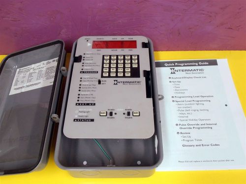
INTERMATIC ET70215CR 4,000 programs 120, 208, 240, or 277 VAC. 50/60Hz 10 W Max.
ATC 342B200F10PX MULTI RANGE REPEAT CYCLE TIMER 24-240VAC NEW IN PKG
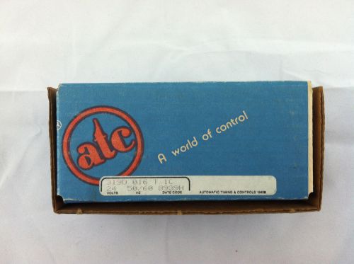
ATC 319D 016 T 1C PLUG-IN ADJUSTABLE TDR TIMING RELAY
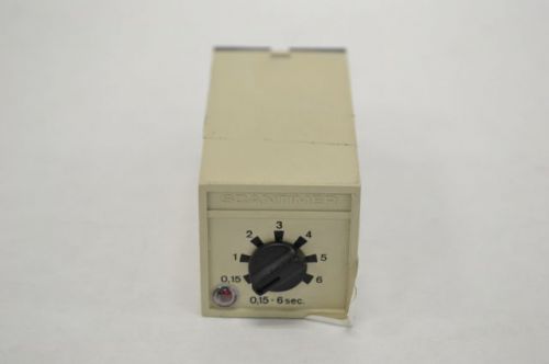
CARLO GAVAZZI A208024 A208024006? SCANTIMER DELAY ON 6SEC 5A RELAY 250V B224901
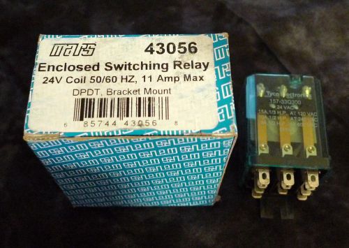
MARS 157-33Q300 Enclosed Switching Relay 24V Coil 50/60HZ 11 Amp Max DPDT 43056
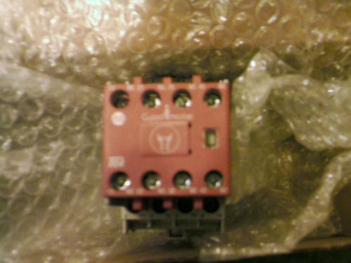
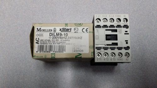
Allen Bradley 100S-C09EJ404C Safety Contactor
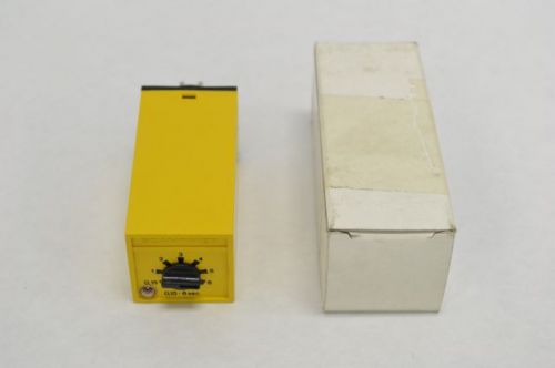
CARLO GAVAZZI A208024006 SCANTIMER DELAY ON 6SEC 5A RELAY 24V-DC 70MA B224894
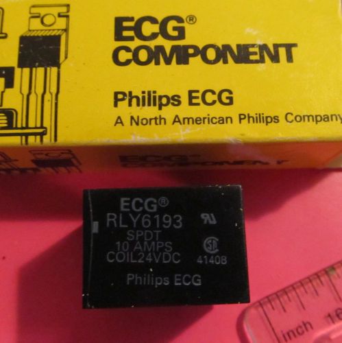
Philips ECG,RLY6193,SPDT,10 Amps 24VDC Coil,(1755WY),41408,5 Pin,1 Pc
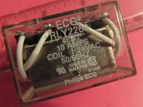
Philips ECG,RLY2263,4 PDT,10Amps Coil 24VAC,(1442W1)50/60Hz,14 Pins,1 PC
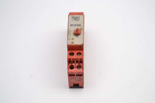
BROYCE M1ESN CONTROL 0.5-10 DELAY 0-60 SEC TIME 250V-AC 8A RELAY B416438
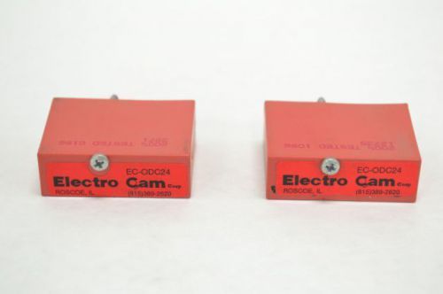
LOT 2 NEW ELECTRO CAM EC-ODC24 OUTPUT RELAY MODDULE B224847
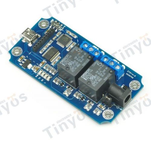
2 Channel USB/Wireless Relay Module (Xbee,Bluetooth,WIFI ) +cell phone control
By clicking "Accept All Cookies", you agree to the storing of cookies on your device to enhance site navigation, analyze site usage, and assist in our marketing efforts.
Accept All Cookies