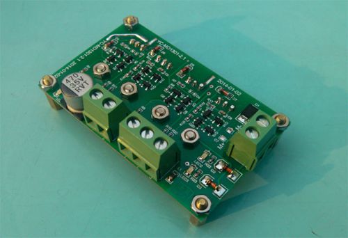
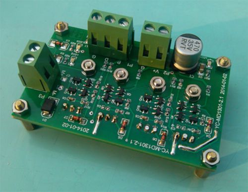
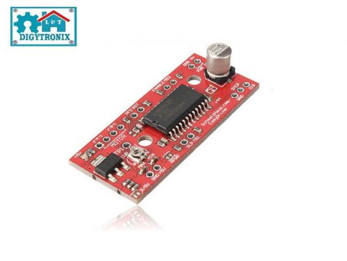
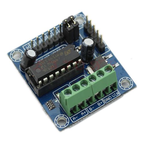
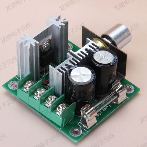
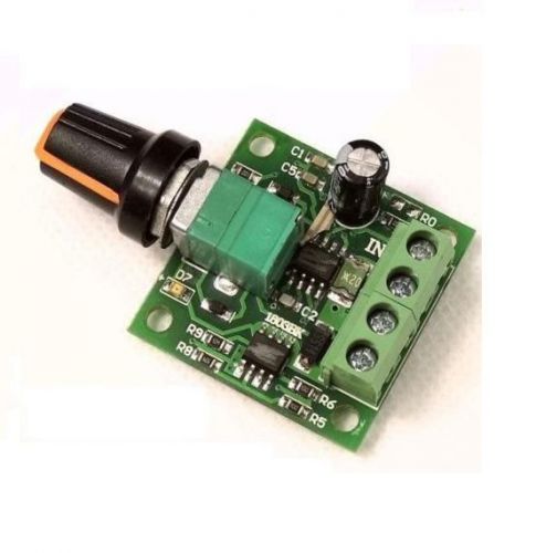
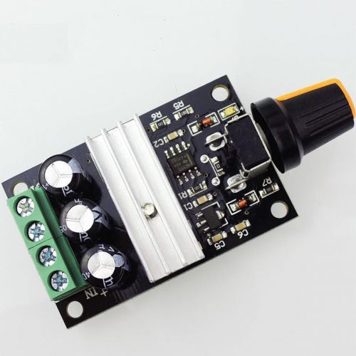
10A Peak 20A 350W DC Motor Driver Board Module H-Bridge DC MOSFET 5V-35V Description: 100% Brand New and High Quality 10A DC motor driver module, using industrial-grade power MOSFET, PWM speed control (available full PWM), reversing switch, emergency brake function, continuous operating current of up to 10A. Using imported 55A power MOSFET, 20 milliohms on-resistance, no heat sink; H-bridge driver circuit design, embedded dead-time control circuit, longer life; Basic parameters: Module name: 10A single-channel DC motor driver module Operating modes: Single H-bridge Key components: 55A M0SFET tube Drive voltage: 5 ~ 35VDC Logic control level: high> 2.5V; low <0.5V Drive Current: 10A Working temperature: 40 ~ 85 °C Rated power: 350W Dimensions: 44 * 71 * 16mm Weight: 50g Features: 1. using industrial-grade power MOSFET tube, continuous current up to 10A, the maximum instantaneous peak current up to 20A, low heat dissipation, no heat sink. 2. Simply put w work for DC power supply, control circuit without additional power supply. 3. saving control of resources, it only takes 2-way MCU I / O control signals, you can achieve PWM speed control, reversing switch, emergency brake function. 4. is compatible with 3V and 5V microcontrollers. 5. motor output has TVS bidirectional protection tube, the motor can quickly drain away from the induced current, protection and control devices. 6. Applications: Smart Cars, robots, finder, industrial control, etc. Port Description: P1- logic control signal input terminal P control signal P input terminal; D control signal D input terminal; G signal reference ground (same as power ground); P2- drive power (electrical power supply) input V+ supply positive range: 5-35VDC; G power ground (with the signal ground connected); P3- drive output M+ positive side driver outputs, connect the DC motor M +; M- negative side driver outputs, connect the DC motor M -; DC motor driver module control logic table: Application Example 1: MCU with a PWM DC motor speed control, reversing switch and brake function, as shown below: Note: If the IO and P, D connection is not strong internal pull-up resistor, you need to add an external pull-up resistor 10K, such as microcontroller 89C51 / 52 series of microcontrollers Programming notes: 1. system power on initialization, it is recommended with P, D connected I / O are set to high (Vh), namely P -> Vh (high); D -> Vh (high); motor in brake status. 2. motor is transferred to start, we recommend using the command: P -> PWM; motor starts forward, forward the process by adjusting the PWM duty cycle (low time and high time ratio) to change the motor real-time speed. Note: PWM pulse width either less than 30us. 3. motor is -> reverse switch, you must first stop the motor brakes that use instruction, P -> Vh (high); D -> Vh (high); brake stops the motor, then 100ms delay so, then perform reverse startup command D-> PWM; motor began to reverse, reverse the course of the motor speed can be adjusted by the PWM duty cycle permits jump (low time and high time ratio). Note: PWM pulse width not less than 30us. 4. motor back -> forward switching, you must first stop the motor brake that, P -> Vh (high); D -> Vh (high); brake stops the motor, then the delay is about 10ms, then run forward startup command P -> PWM; motor begins to move forward. 5. Motor emergency stop (braking), perform a combination of instruction: P -> Vh (high); -; no other instructions between the two instructions after the order can not be reversed, and D> Vh (high). Application Example 2: Button realized by a simple DC motor reversing switch and brake function, as shown below: Do gymnastics Description: K1 start button for the motor is transferred, K2 for motor reversal start button, K3 brakes for motor forward button. K1 button is pressed, the motor runs forward at this time, lift buttons K1, the motor coasts to stop running. K2 button is pressed, the motor reverse run, this time, the lift button K2, the motor coasts to stop running. When the motor is in forward or reverse, press K3 direct button, the motor is braking, immediately stop running. Load test: 1. connect to 2.4 ohm power resistors, power supply 24VDC, PWM control signal frequency 20kHz, 90% duty cycle, the output current of 8.83A, as shown below: 2 . connect to 2.4 ohm power resistors, power supply 24VDC, PWM control signal frequency 20kHz, the duty cycle of 100%, the output current of 10.22A, as shown below: Programming examples: Connection with MCU STC15F2K60S2 DC motor drive control board module, DC motor reversing, braking control; electrical connection diagram, as follows: rogram files, as follows: / * ------------------------------------------------ ------------------ * / / * --- Morning electronic design studio ---------------------------------------- --- * / / * --- STC15F2K60S2 connected DC motor driver module routines ------------------------ * / / * --- Moble: (86) 13911042053 --------------------------------------- * / / * --- Tel: 86-010-51678689 -------------------------------------- - * / / * --- Web: http://shop58601044.taobao.com ------------------------- * / / * --- QQ: 285331517 ------------------------------------------ ---- * / / * ------------------------------------------------ ------------------ * / / ************* Function Description ********************************** ******** This program demonstrates the use of SCM STC15F2K60S2 DC motor drive control board connection module, DC Reversible motors, brake control; By doing 16 Timer 0 auto reload, interrupts, IN11 and IN12 output from PWM. Achieved through an external interrupt 0 keys KEY1, KEY2 collection and response; PWM can be any range. However, due to reinstall the software needs a little time, so a minimum PWM duty cycle 32T / cycle, maximum (cycle -32T) / cycle, T is the clock cycle. PWM frequency is reciprocal of the period. If the period of 2400 to use 24MHZ frequency, the PWM frequency is 10kHZ. ************************************************** ******************** / #include <reg52.h> # defineMAIN_Fosc24000000UL // definition master clock # definePWM_DUTY2400 // definition PWM cycle, the value is the number of clock cycles, use 24MHZ frequency, the value is 2400, PWM frequency is 10kHZ. # definePWM_HIGH_MIN32 // limit minimum duty cycle of the PWM output. Do not modify the user. #definePWM_HIGH_MAX (PWM_DUTY-PWM_HIGH_MIN) // limit maximum duty cycle of the PWM output. Do not modify the user. typedefunsigned charu8; typedefunsigned intu16; typedefunsigned longu32; sfr P3M1 = 0xB1; // P3M1.n, P3M0.n = 00 ---> Standard, 01 ---> push-pull sfr P3M0 = 0xB2; // = 10 ---> pure input, 11 ---> open drain sfrAUXR = 0x8E; sfr INT_CLKO = 0x8F; // sbitP_PWM = P3 ^ 5; // define the PWM output pin. // sbitP_PWM = P1 ^ 4; // define the PWM output pin. STC15W204S sbit IN11 = P3 ^ 3; // motor control interface --P sbit IN12 = P3 ^ 4; // motor control interface --D sbit BEEP = P3 ^ 7; // buzzer sbit KEY1 = P2 ^ 0; // button 1, press the motor is transferred, then press the motor is stopped, then press the motor is transferred sbit KEY2 = P2 ^ 1; // button 2, press the motor reversal, then press the motor is stopped, then press the motor reversal u16pwm; variable @ PWM output high definition time. User operation PWM variables. u16PWM_high, PWM_low; // intermediate variables, users do not modify. u8T0Countor; // T0 count variable u8 M0Run; // do gymnastics state variable motor 0 0 --- Stop, Forward 1 --- 2 --- reversal, void delay_ms (unsigned char ms); voidLoadPWM (u16 i); / ******************** Main function ************************** / void main (void) { // P_PWM = 0; IN11 = 0; IN12 = 0; BEEP = 0; P3M1 & = ~ (1 << 3); P3M0 | = (1 << 3); // P3.3 IN11 is set to push-pull output P3M1 & = ~ (1 << 4); P3M0 | = (1 << 4); // P3.4 IN12 is set to push-pull output P3M1 & = ~ (1 << 7); P3M0 | = (1 << 7); // P3.4 IN12 is set to push-pull output TR0 = 0; // stop counting ET0 = 1; // allowed to interrupt PT0 = 1; // high priority interrupt TMOD & = ~ 0x03; // mode, 0:16-bit auto-reload AUXR | = 0x80; // 1T TMOD & = ~ 0x04; // timing // INT_CLKO | = 0x01; // T0Clock output clock TH0 = 0; TL0 = 0; TR0 = 1; // starts running INT0 = 1; // allow INT0 interrupt IT0 = 1; // Set INT0 interrupt type 1 --- 0 --- only the falling edge of the rising and falling EX0 = 1; // Enable INT0 interrupt EA = 1; pwm = (PWM_DUTY * 2) / 10; // to PWM an initial value, for example PWM_DUTY / 10 when 10% duty cycle; (PWM_DUTY * 2) / 10 when 20% duty cycle; (PWM_DUTY * 3) / 10:00 for 30% duty cycle; LoadPWM (pwm); // calculate the PWM reload value M0Run = 0; // set the initial state of the motor, 0 --- Stop, Forward 1 --- 2 --- reversal, while (1) { } } @ ================================================ ============ @ Function: void delay_ms (unsigned char ms) @ Description: The delay function. @ Parameters: ms, the number of ms to delay, here only supports 1 ~ 255ms automatically adapt to the master clock. @ Return: none. @ Version: VER1.0 @ Date: 2013-4-1 @ Notes: @ ================================================ ======================== void delay_ms (unsigned char ms) { unsigned int i; do { i = MAIN_Fosc / 13000; while (- i); } while (- ms); } / **************** Calculate the PWM reload value function ******************* / voidLoadPWM (u16 i) { u16 j; if (i> PWM_HIGH_MAX) i = PWM_HIGH_MAX; // If the write data is greater than the maximum duty cycle is forced to the maximum duty cycle. if (i <PWM_HIGH_MIN) i = PWM_HIGH_MIN; // If writing is less than the minimum duty cycle data is mandatory for a minimum duty cycle. j = 65536UL - PWM_DUTY + i; // calculate the PWM low time i = 65536UL - i; // calculate the PWM high time EA = 0; PWM_high = i; // loading PWM high time PWM_low = j; // loading PWM low time EA = 1; } / ********************* INT0 interrupt function ************************ / void exint0 () interrupt 0 { if (KEY1 == 0) // button 1 Press { if (M0Run == 0) M0Run = 1; // when the motor is stopped, the motor is transferred; else M0Run = 0; // Otherwise, the motor stops; } If (KEY2 == 0) // button 1 Press { if (M0Run == 0) M0Run = 2; // when the motor is stopped, the motor reversal; else M0Run = 0; // Otherwise, the motor stops; } BEEP = 1; delay_ms (20); BEEP = 0; } / ********************* Timer0 interrupt function ************************ / void timer0_int (void) interrupt 1 { if (M0Run == 0) { IN11 = 1; IN12 = 1; T0Countor = 0; } if (M0Run == 1) { T0Countor ++; if (T0Countor == 1) { IN12 = 0; TH0 = (u8) (PWM_low >> 8); // If the output high -> low, low loading time. TL0 = (u8) PWM_low; } if (T0Countor == 2) { IN12 = 1; T0Countor = 0; TH0 = (u8) (PWM_high >> 8); // output if it is low -> high, the load high time. TL0 = (u8) PWM_high; } } if (M0Run == 2) { T0Countor ++; if (T0Countor == 1) { IN11 = 0; TH0 = (u8) (PWM_low >> 8); // If the output high -> low, low loading time. TL0 = (u8) PWM_low; } if (T0Countor == 2) { IN11 = 1; T0Countor = 0; TH0 = (u8) (PWM_high >> 8); // output if it is low -> high, the load high time. TL0 = (u8) PWM_high; } } } Package included : 1x Single Channel 10A DC Motor Driver Module Board SHIPPING All the items will be dispatched within 1 business day by Hong Kong Airmail after the payment is clear. Items will arrive in 7-25 business days. The arrival time depends on some factors and different areas: Please choose some local sellers, if you cannot wait patiently in the shipping time we declared. Once you purchase, please DON’T leave negative or neutral feedback if you haven’t received item in 30 days, because we have mentioned the shipping time repeatedly. Customs duty is obligation and liability of a citizen in your country, so buyer should be responsible for any tax and custom duty incurred. For example, Laser Pointer is unacceptable in some countries. Therefore, please double check your local customs policy carefully before purchase. Or, we will NOT be responsible for any failure delivery related destination customs issue. PAYMENT We accept PayPal only. We only ship item to your PayPal verified address. Payment must be received within 3 Days from the date of purchase. Please leave note in PayPal when making the payment if you have any special request (colors/size). Orders will be processed instantly and dispatched in same day normally, so we do NOT accept any Email/Message note before or after you place orders. REFUND & REPLACEMENT POLICY All the products we are selling include factory warranty, don’t cover items that have been abused, burned and damaged in any form. Please contact us via eBay Message if you have NOT received item in 30 days, we will check it with post office, and then resend or refund any missing item. In the unlikely event that your product is faulty in anyway, you must contact us ASAP and then return it within 7 Days of receipt. The postage and packaging fee will NOT be refunded. We will not be responsible for the delivery or insurance charges incurred in returning item back to us. If you return an item purchased from us, it must be back in Factory Condition. This includes packaging, inserts, manuals etc. Please allow up to 5 Working Days for us to process your returned item. FEEDBACK & CONTACT US If you have any questions, please feel free to email our service specialists 24 Hours a Day, 7 Days a Week. We will reply you ASAP. If no response within 24 Hours, please check the spam in your mail box. We greatly appreciate your POSITIVE feedback. Please do NOT leave negative feedback without asking for help. Our aim is to provide Top Level Customer Service, normally so we will try our best to solve any problem. Please DON’T leave negative or neutral feedback if you haven’t received item in 30 days, because we have mentioned the shipping time repeatedly. On Sep-21-14 at 18:15:40 PDT, seller added the following information: On Dec-27-14 at 23:10:52 PST, seller added the following information:
By clicking "Accept All Cookies", you agree to the storing of cookies on your device to enhance site navigation, analyze site usage, and assist in our marketing efforts.