


US $12.88
Directions
Similar products from Development Boards & Programmers
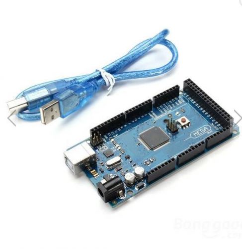
Mega2560 R3 ATmega2560-16AU Control Board With USB Cable For Arduino
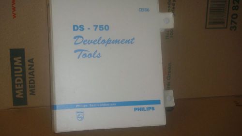
PHILIPS CEIBO DS-750 DEVELOPMENT TOOLS FOR 87C750

Fast RISC microcontroller ATmega128 with up to 16 MIPS throughput
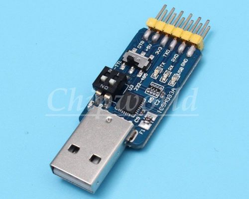
New ICSH033A CP2102 multifunction Serial Module 3.3V and 5V input voltage
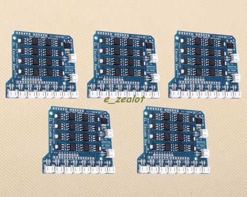
5pcs ICSJ015A EL Escudo Dos Shield for Arduino + free tracking number
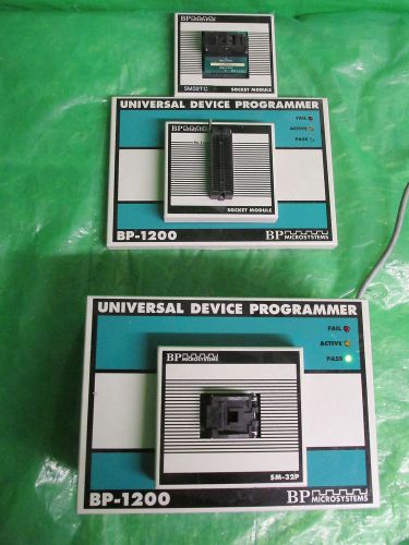
BP Microsystems BP-1200 Universal Device Programmer Power Tested
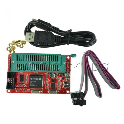
Microcontroller/24/93 Series EEPROM Programmer memory chip Boost SP200S/SP200SE
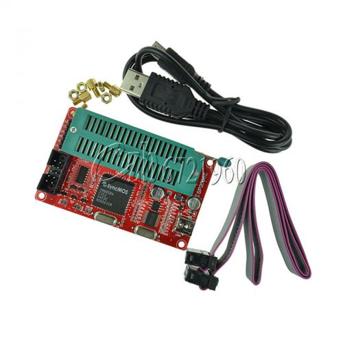
Microcontroller/93/24 Series EEPROM Programmer memory chip Boost SP200SE/SP200S
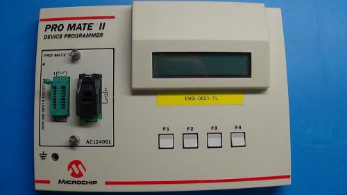
Microchip Pro Mate II Device Programmer
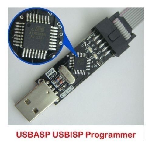
New USBASP USBISP AVR Programmer USB ATMEGA8 ATMEGA128

Pic Start Plus Programmer And Picstart 16B1 Lite

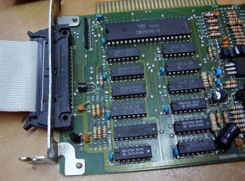
Vintage MCT EEprom Eprom Programmer system / Card & ZIF unit
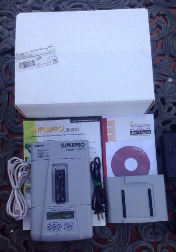
Xeltek Superpro 3000U Eprom Programer
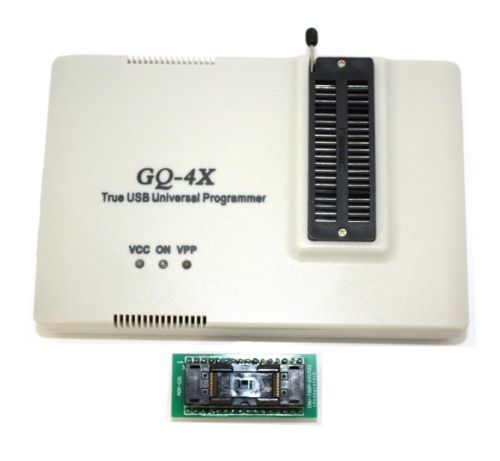
Programmer Plus Adapter True USB Willem Light Pack+ADP-021 PRG-115 GQ-4X
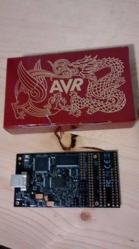
Atmel AVR Dragon Programmer Debugger
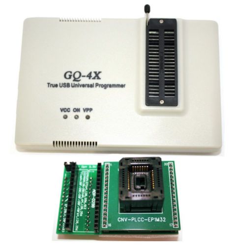
Willem Programmer Light Pack+ADP-029 PRG-114 GQ-4X
People who viewed this item also vieved
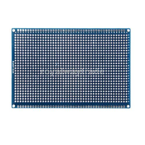
Double Side Prototype PCB Universal Printed Circuit Board Peg Board 8x12cm
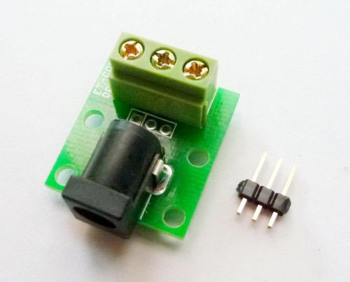
ADAPTER - DC Power Jack 2.5 mm Breakout to PIN HEADER & TERMINAL
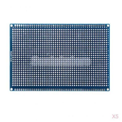
5Pcs Double Side Prototype PCB Universal Printed Circuit Board Peg Board 8x12cm
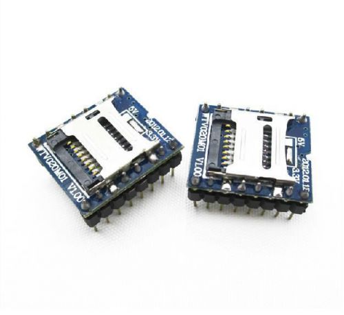
MP3 Voice module U-disk audio player SD card voice module WTV020-SD-16P s
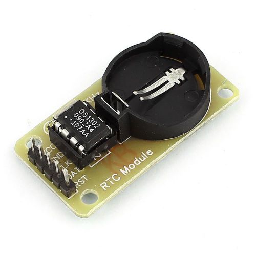
10PCS Arduino RTC DS1302 Real Time Clock Module For AVR ARM PIC SMD NEW
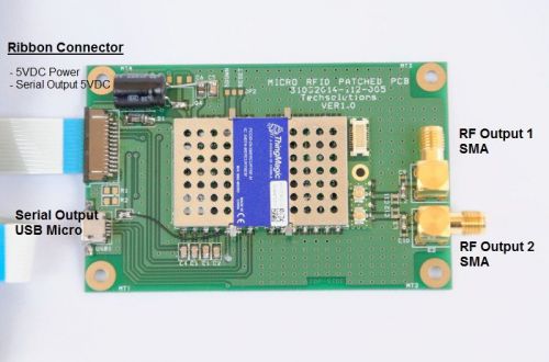
Thingmagic UHF RFID reader module with USB for Raspberry Pi

Sofasco Axial AC Fan Model A17251V1HBT 100-125 VAC 50/60 Hz Thermal Protected

Oriental Motor Orix MDS1225-24 MDS122524 DC Brushless New No Box

Sanyo Denki 109S024UL Axial Fan
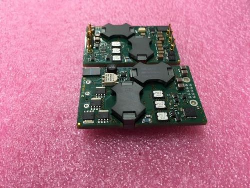
1pc of BMR453-0000/001S Ericsson Isolated DC/DC Converter 400W 36-75Vin / 12Vout
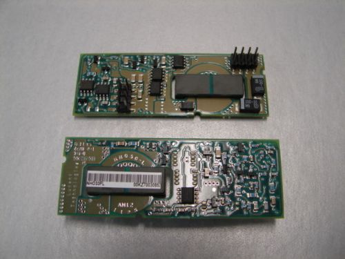
1 pc of NH033F-L Lucent CONVERTER DC/DC 3.3V 33W OUT - New -
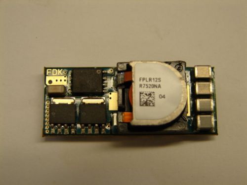
1 pc of FPLR12SR7520NA FDK Non-Isolated DC/DC Converter 6-14Vdc In, 2008dc, ROHS
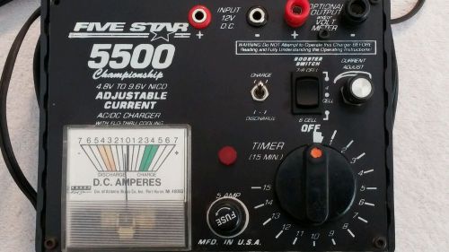
Five Star Chargers 5500 Championship, Adjustable Current AC/DC Charger
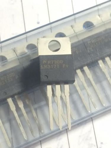
(45 COUNT) NEW OLD STOCK (NOS) LM317 LM317T LINEAR VOLTAGE REGULATOR IC #1
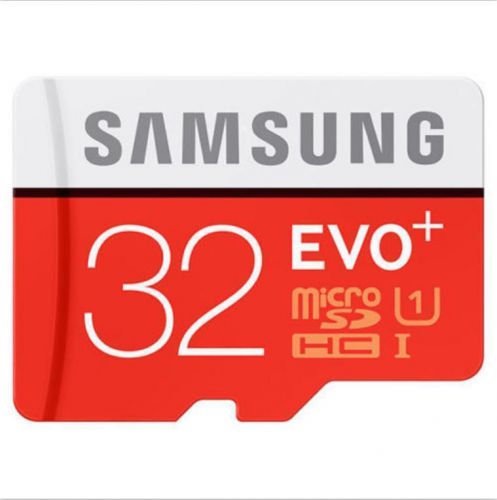
samsung evo 32gb microsd card 32 gb class10 memory cards class 10
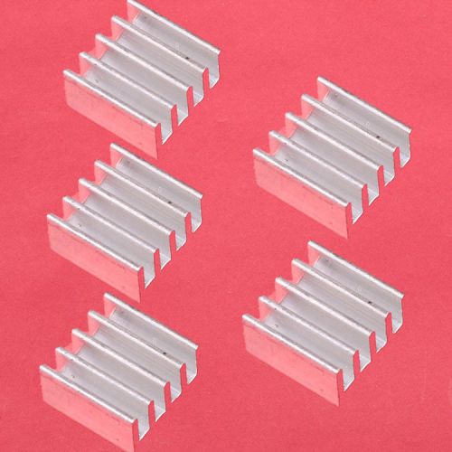
5PCS 3M8810 IC Heat sink Aluminum 13*13*7MM Cooling Fin ADHESIVE 13X13X7MM
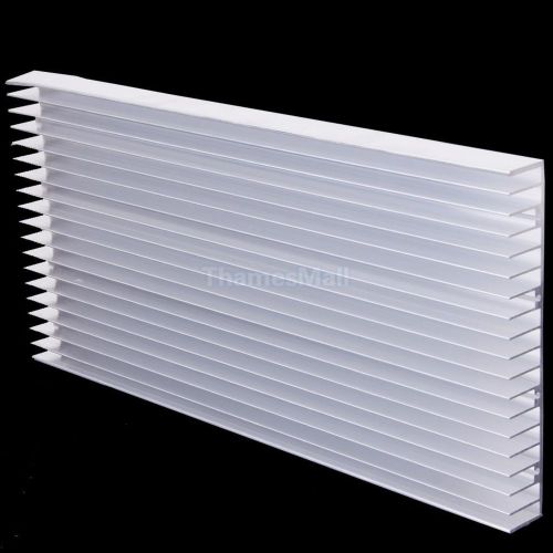
300x140x20mm Aluminum HeatSink for 8x3w/20x1w LED & Power IC Transistor Module
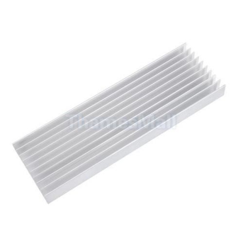
Aluminum Heatsink Cooling Heat Sink for 5x3W / 10x1W LED Light Power Transistor
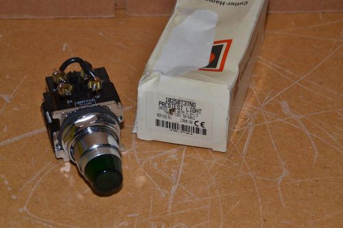
CUTLER HAMMER 10250T37NG GREEN LENS 120V 50/60Hz SER B1 PRESTEST LIGHT NEW
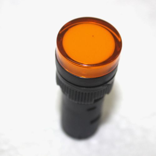
AC 220V 16MM Hole Yellow LED Pilot Dash Light AD16-16C 20mA Max Current
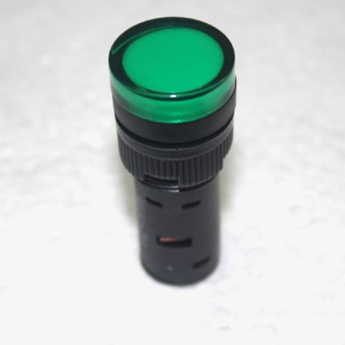
AC 220V 16MM Hole Green LED Pilot Dash Light AD16-16C 20mA Max Current
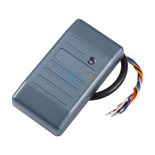
Black Proximity RFID EM ID Cards Reader For Wiegand 26 RS485 RS232 ABA
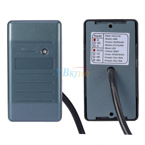
125KHz Waterproof Proximity RFID EM ID Cards Reader For Wiegand 26 RS485
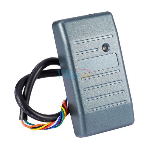
DC 8-15V Proximity RFID EM ID Cards Reader For Wiegand 34 RS485 RS232 ABA
By clicking "Accept All Cookies", you agree to the storing of cookies on your device to enhance site navigation, analyze site usage, and assist in our marketing efforts.
Accept All Cookies
