
US $155.00
| Condition: |
New: A brand-new, unused, unopened, undamaged item in its original packaging (where packaging is
applicable). Packaging should be the same as what is found in a retail store, unless the item is handmade or was packaged by the manufacturer in non-retail packaging, such as an unprinted box or plastic bag. See the seller's listing for full details.
...
|
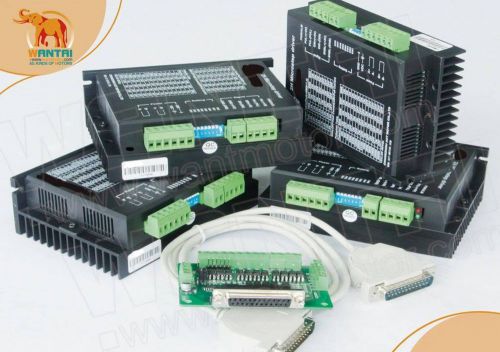
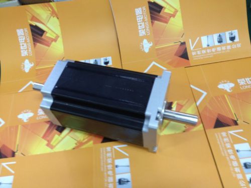
Brand | Wantai Motor |
| MPN | Does Not Apply |
Directions
Similar products from Stepper Motor Driver Boards & Modules

CNC Router Nema34 Gear Stepper Motor Ratio 50:1 2 phase 4 leads 4A 150NM new
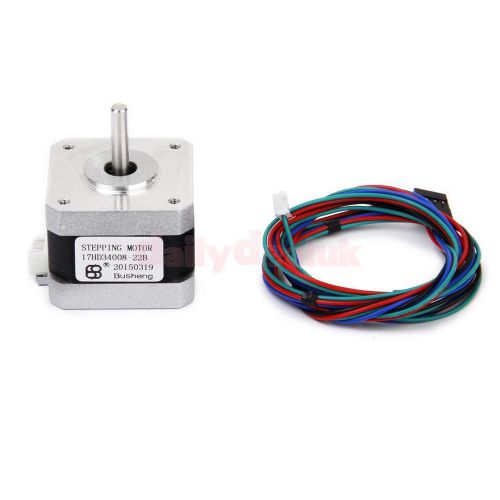
NEMA17 HoldingTorque 300mN.m Stepper Motor 1.8deg for 3D Printer CNC
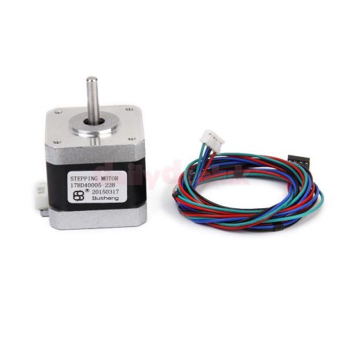
NEMA17 360mN.m Two-phase 4-wire Step Stepper Motor 1.8deg for 3D Printer CNC
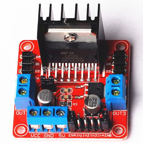
L298N Module Dual H Bridge Stepper Motor Driver Board Modules for Arduino
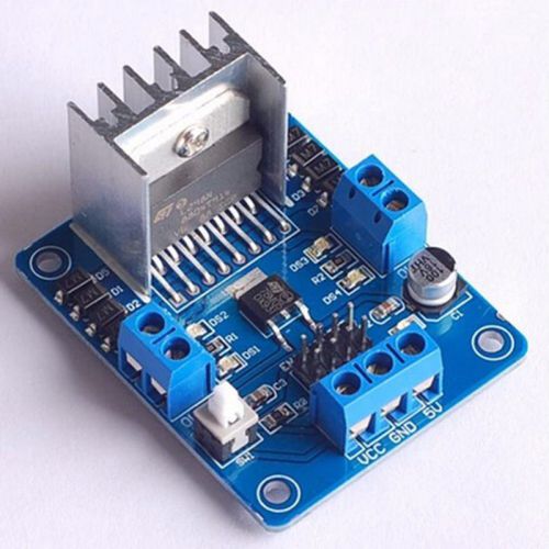
L298N Motor Mriver Blue New original L298N motor driver board module for Arduino
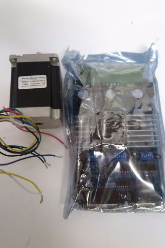
3 axis tb6560 cnc stepper motor driver controller/wantai step motor 57BYGH633
?German Ship?3 pcs Nema 23 stepper motor 270 oz.in=1.9NM ,3A 23HS8430 bipolar
?Free ship?CNC 3PCS NEMA42 Stepper Motor4120 oz.in, 4 leads, 8A Dual shaft CNC
CNC 1PC NEMA42 Stepper Motor4120 oz.in, 4 leads, 8A Dual shaft CNC Brigeport
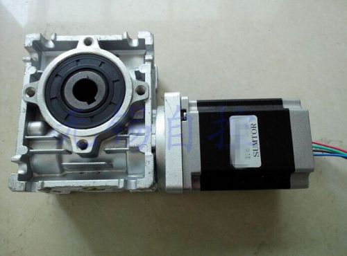
CNC Worm Gear Stepper Motor Ratio 7.5:1 NEMA23 L 112mm 4.2A57HS11242RV30G75 new

New CNC Single Axis TB6600 4.5A Two Phase Stepper Motor Driver Controller

ULN2003 Stepper Motor Driver Board Test Module Board for Arduino Driver Mega New

Geeetech EasyDriver Shield stepping Stepper Motor Driver A3967 For Arduino

57mm Worm Gear Stepper Motor Ratio 30:1 NEMA23 L 112mm 4.2A 57HS11242RV30G30 new

Nema17 stepper motor 0.9degree /48mm/ 78 Oz-in / 1.8A - CNC Mill 3D Printer
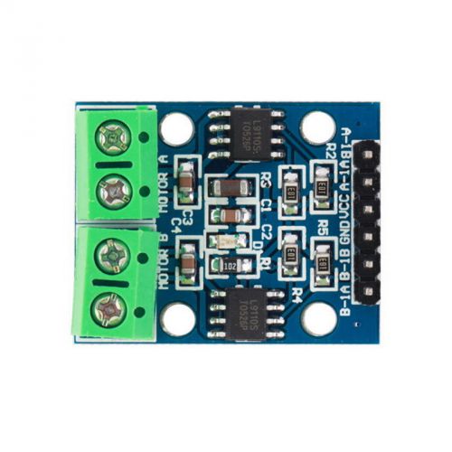
L9110S H-bridge Stepper Motor Dual DC motor Driver Controller Board LJN

1PC NEW LeadShine MA860H 2,4 Phase Stepper Motor Drive Up to 80VAC/110VDC 7.2A

L9110S DC H-Bridge Stepper Motor Driver Controller Module for Arduino A938 DH

Dual H Bridge Stepper Motor Drive Controller Board Module For Arduino L298N E2

H-bridge Stepper Motor Dual Motor Driver Controller Board HG7881 Fr Arduino BYWP
People who viewed this item also vieved

TELEMECANIQUE LR2 D1310 LR2 D13 4-6A THERMAL MOTOR OVERLOAD RELAY NEW

BRINKMANN PUMPS TB 16/220-GZ+416 IMMERION PUMP 230/460V 0.25/0.5A 60HZ, NEW*


Motor Control Board PL-8794700AC
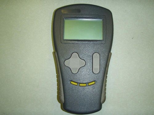
Curtis Handset Model # 1311-4401 - Rent Per a Month
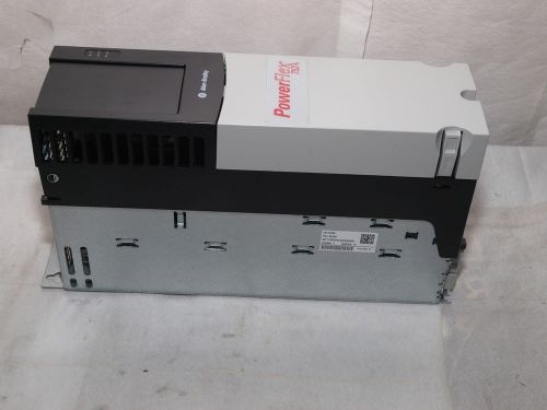
Allen-Bradley PowerFlex 753AC Drive 20F11RD5P0AA0NNNNN + 20COMM Adapter Plate

Lot of 3 TELEMECANIQUE CA2 Contactors FT111,FN162,FN131 10 amp

DANFOSS CYCLETROL 150 MOTOR SPEED CONTROL DC DRIVE 120 VAC 176B6004


NEW DANFOSS CYCLETROL 150 MOTOR SPEED CONTROL DC DRIVE 120 VAC 150303

HC HEAD PRESSURE CONTROLLER VARIABLE MOTOR SPEED for CONDENSING UNIT 800 series
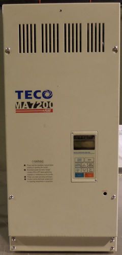
Teco MA7200 PLUS AC inverter / adjustable speed drive MA7200-4060-N1 UNTESTED

Teco MA7200 PLUS AC inverter / adjustable speed drive MA7200-4040-N1 UNTESTED

Danfoss 176B1111 DC Speed Control, 120VAC IN, 90VDC OUT
New Sealed Allen Bradley 40420-322-51 Contact Kit for Bulletin 500 Contactor Qty
SIEMENS DC CONTACTOR No. 14-193-100-582 1000V 1250ADC COIL 125VDC
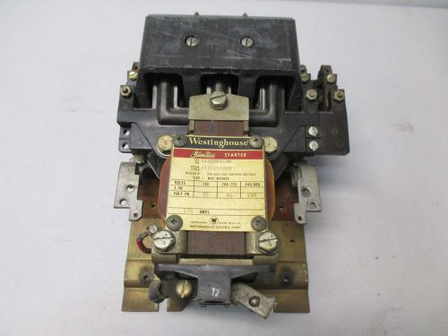
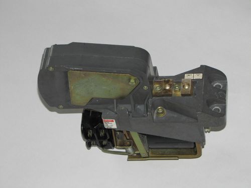
WESTINGHOUSE 11200K4CNN LIFE-LINE 440V-AC 100HP 135A SIZE 4 AC CONTACTOR D425629
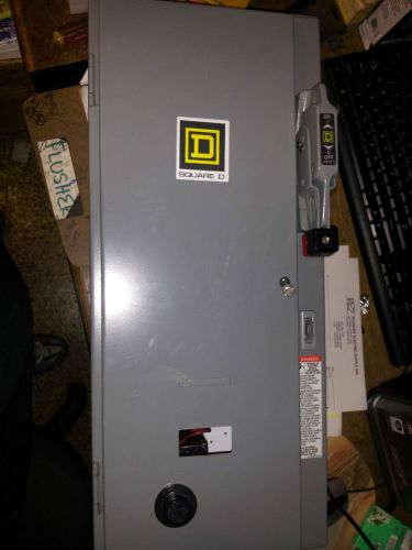
SQUARE D 8538SBG11V81CFF4H309T SIZE 0 STARTER/DISC COMBO NEMA 1 NEW NO BOX #A28
NEW CUTLER HAMMER AE56AN0CC 480V-AC 5HP 7A AMP REVERSING MOTOR STARTER D379816
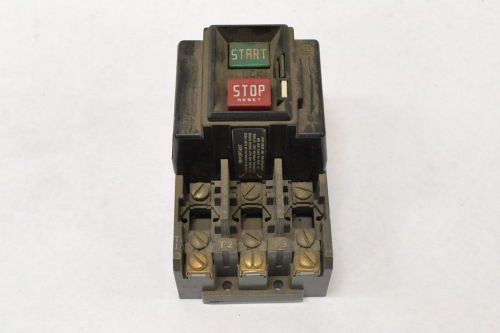
ALLEN BRADLEY 609-BOW 460-575 3 PHASE SIZE 1 MANUAL 10HP MOTOR STARTER B287210

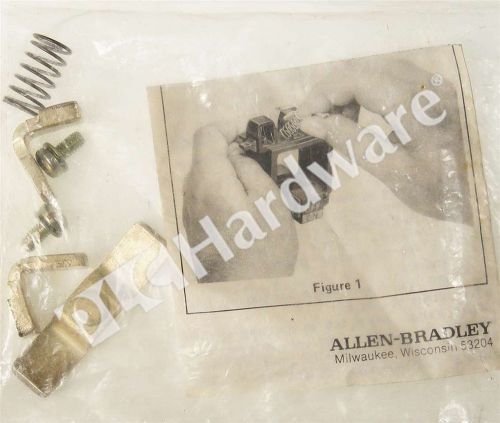
NEW ALLEN-BRADLEY X-247278 CONTACT KIT SIZE 0 3 POLE
By clicking "Accept All Cookies", you agree to the storing of cookies on your device to enhance site navigation, analyze site usage, and assist in our marketing efforts.
Accept All Cookies