US $19.18
Directions
Similar products from Voltage Converters & Meters
8A DC-DC Step up Power Module Booster Module Converter for Arduino Raspber DC-DC
Universal Battery Charger Module, Constant C/V, ST L200
5AMP Adjustable Voltage Regulator Module, External Pot.

Voltage regulator FoMoCo genuine parts ford family of fine cars 1940s-1960
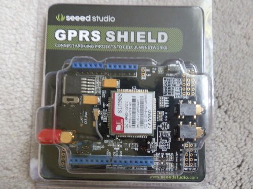
Seeed Studio GPRS shield for arduino to Celluar Network New In Package
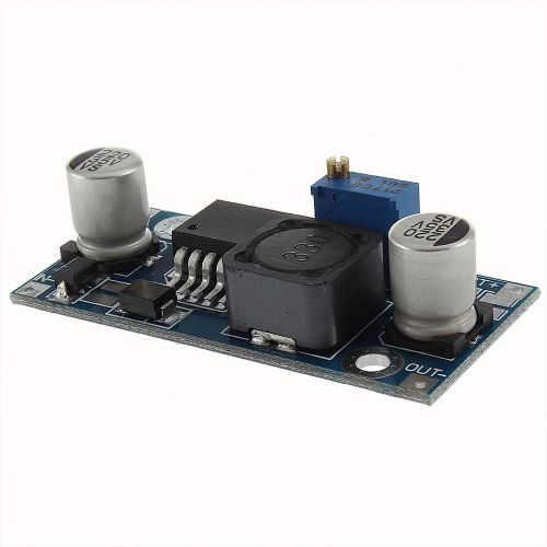
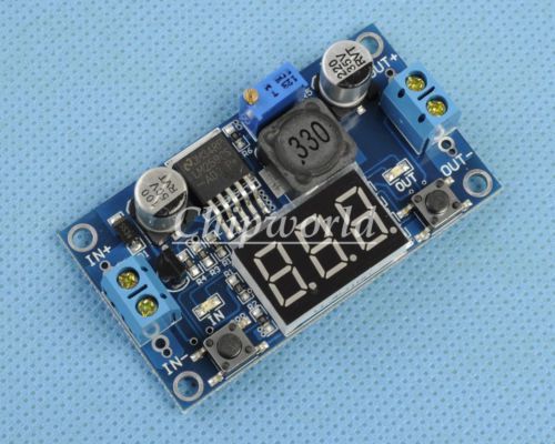
1 Pcs DC-DC Buck Converter Step Down Module LM2596 Power Output 1.23V-30V WW
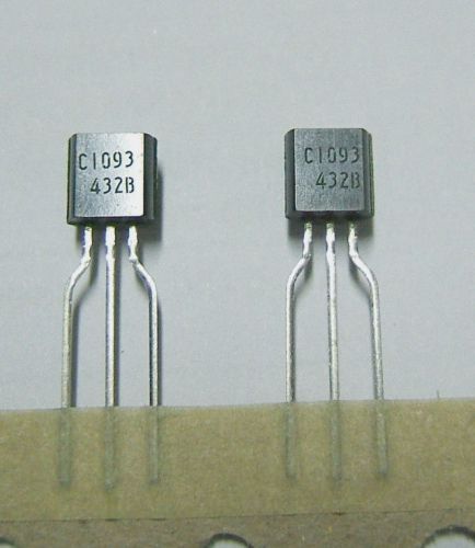
15x NEC UPC1093 Adj precision shunt regulators
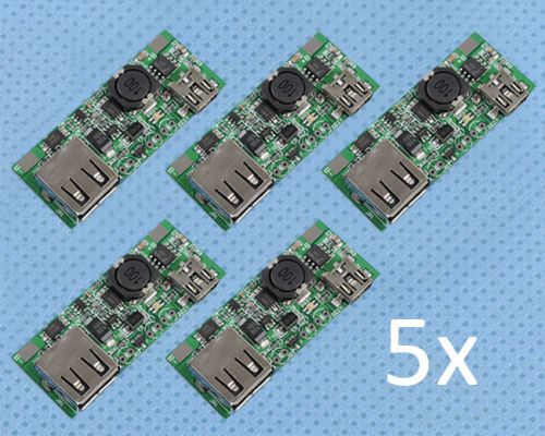
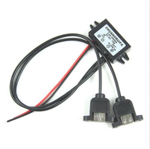
5PCS MINI USB to USB A Power Apply Module 5V 1A Charge Module female port
5pcs DC-DC 3.5V-28V to 1.25V-26V Converter Step Up Step Down Module
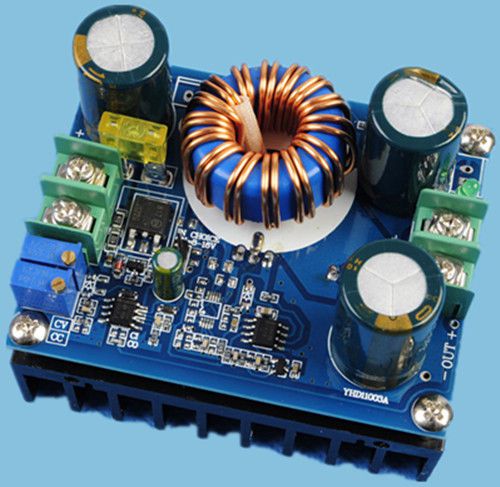
DC-DC Step Up Power Apply Module 12V-60V to 12V-80V High-Power 600W
10PCS 5A LED Drive Power Supply Module Step Down CVCC 75W Battery Charger
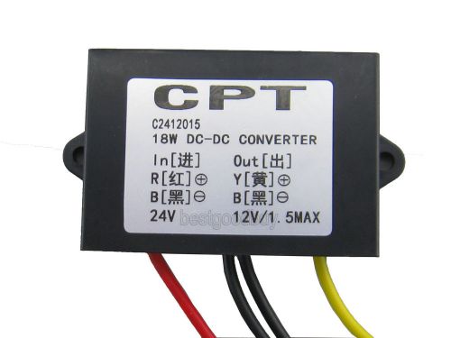
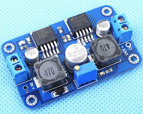
17-35V to 12V DC to DC buck converter car power supply volt Regulator 12V to 5V
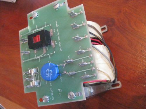
Power Transformer Tower Lighting Systems cell antenna radio billboard TLS htf
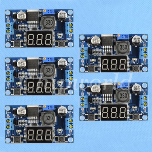
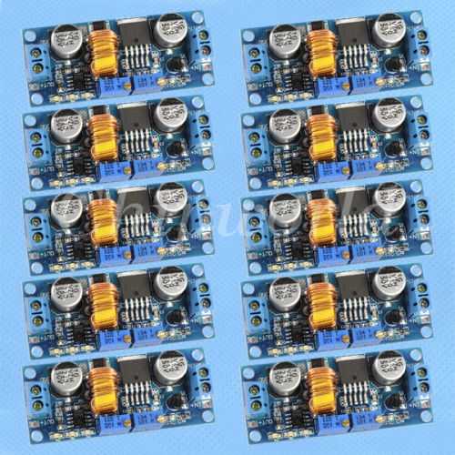
10pcs LM2596 DC-DC Step Down Power Module 4.2V-40V to 1.25V-37V Converter
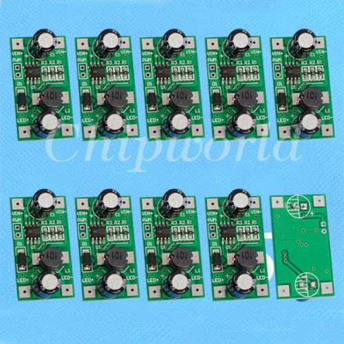
10pcs 1W LED Driver 350mA PWM Light Dimmer DC-DC Step Down Module
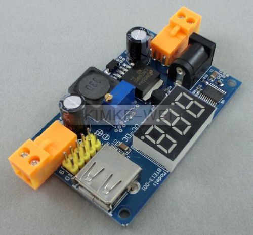
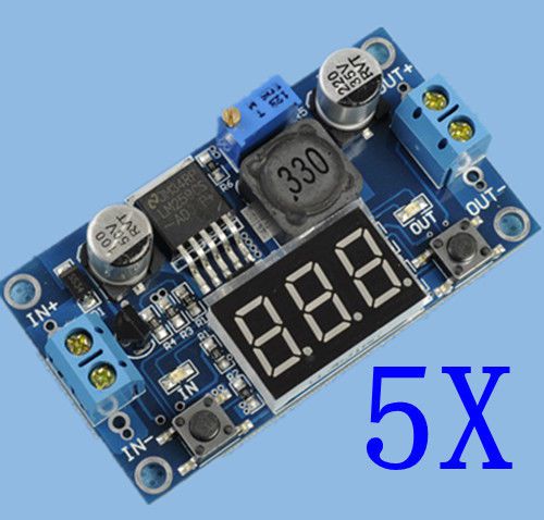
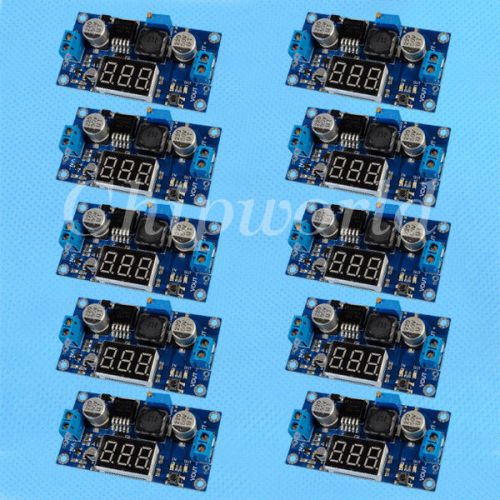
LM2596 USB DC-DC Step Down Adjustable Power Supply Module & LED Voltmeter/Needle
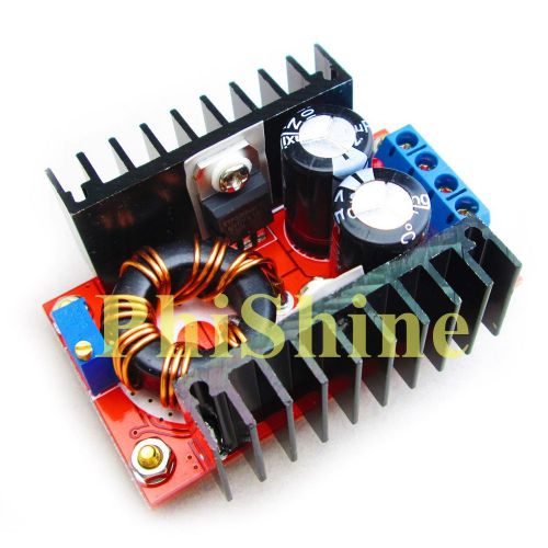
DC-DC 10-32V to 12-35V 150W Power Supply Module Adjustable Boost Module
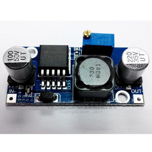
New LM2596S DC-DC Adjustable Step Down Power Module Input 3V-40V Output 1.5V-35V
People who viewed this item also vieved
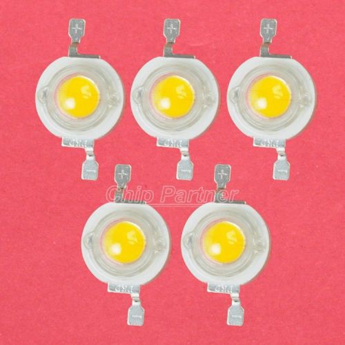
5pcs 3W Warm White High Power LED 200-220LM SMD 3000-3500K

10x 1210 3528 SMD LED surface mount 5000mcd Ultra bright Pink leds lights parts
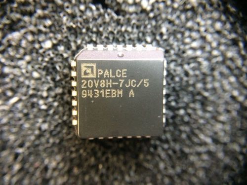
PAL20V8H-7JC/5 AMD IC 20V8 EPLD 14IN 8OUT 7.5 PLCC 2 PIECES
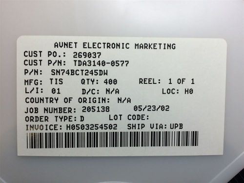
SN74BCT245DW TEXAS INSTRUMENT IC BUS TRANSCEIVER 8BIT 20SOIC 10 PIECES
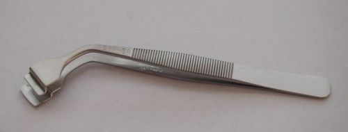
Curved Shank Wafer Handling Tweezer Made In Switzerland
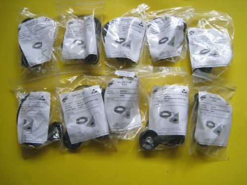
Lot of 10 NEW 15 Feet Floor Ground Cords 1 Meg Resistor FGC151M
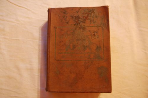
Motorola Semiconductor Data Book, 1969 Fourth Edition (4th Ed) Reference Manual
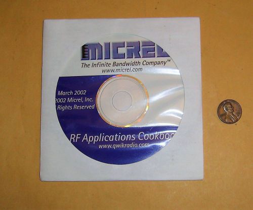
RF Applications Cookbook Disc by Micrel Inc. - 2002
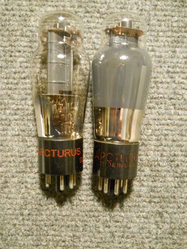
2) Arcturus 25L6G Antique Power Amplifier Vacuum Tube ~ TV-7 Tested
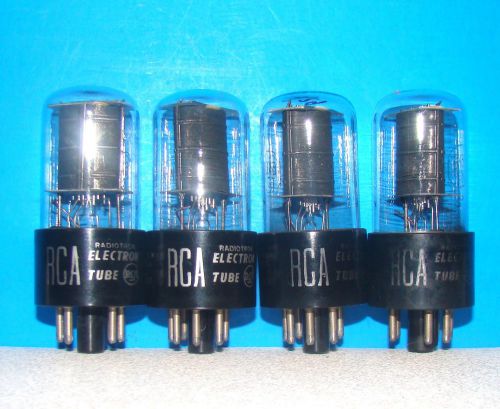
6K6GT vacuum tubes 4 valves RCA radio amplifier vintage electronic tested 6K6G
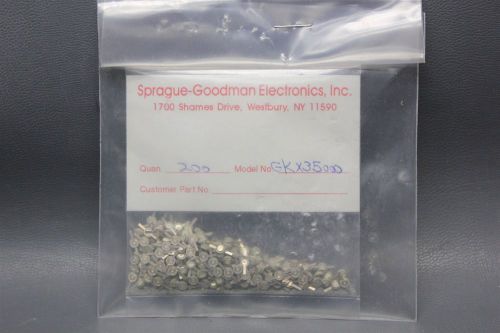
200pcs NEW SPRAGUE TRIMMER/VARIABLE CAPACITOR 6-35PF 25VDC GKX35000 (S12-1-140A)
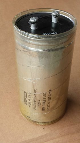
240000 uf Electrolytic Capacitor
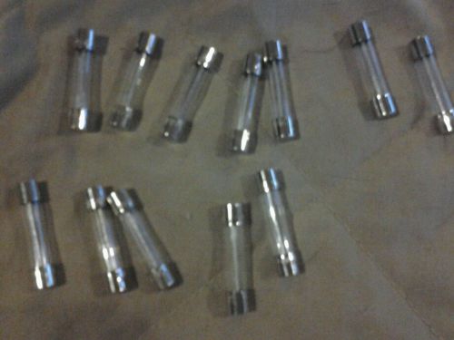
12 lot littlefuse h313015 313 1.5a /250v glass fuse 1.5 amp a
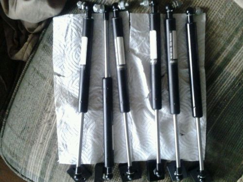
One Suspa c16-07546 gas spring cylinder
By clicking "Accept All Cookies", you agree to the storing of cookies on your device to enhance site navigation, analyze site usage, and assist in our marketing efforts.
Accept All Cookies