


US $24.66
| Condition: |
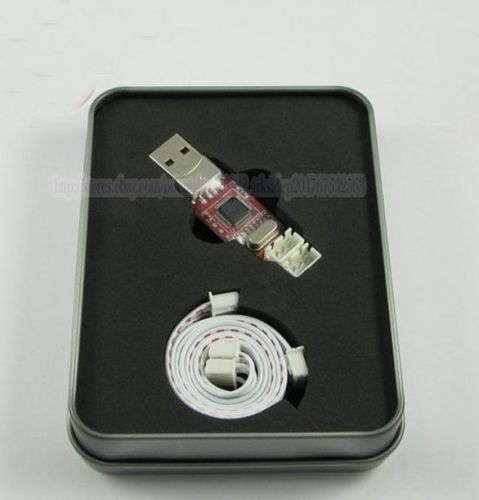
New: A brand-new, unused, unopened, undamaged item in its original packaging (where packaging is
applicable). Packaging should be the same as what is found in a retail store, unless the item is handmade or was packaged by the manufacturer in non-retail packaging, such as an unprinted box or plastic bag. See the seller's listing for full details.
...
|
MPN | OEM |
| Country/Region of Manufacture | China |
Directions
Similar products from Development Boards & Programmers
microcontrollers PICkit2 PIC KIT2 debugger programmer for PIC dsPIC PIC32 PIC24
STLINK V2 ST-LINK STM8 STM32 Emulator Downloader
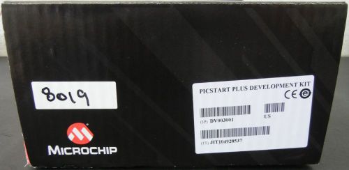
MICROCHIP TECHNOLOGY PROGRAMMER P/N DV003001
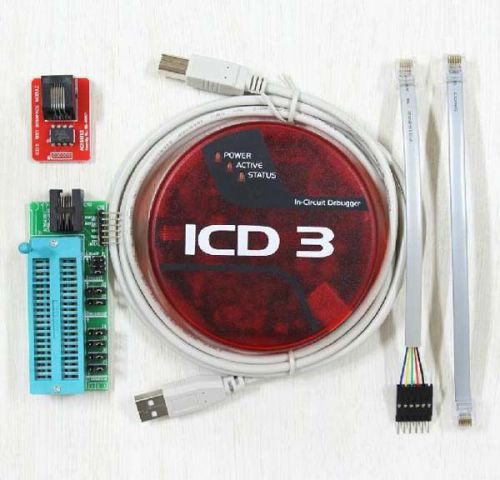
MPLAB ICD 3 In-Circuit Emulator/Debugger/Programmer Development tool for PIC MCU
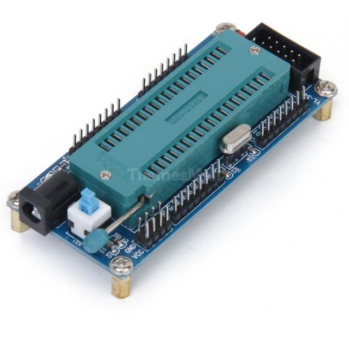
ISP ATMEGA16 ATmega32 Mini System Board AVR Minimum System Development Board DIY
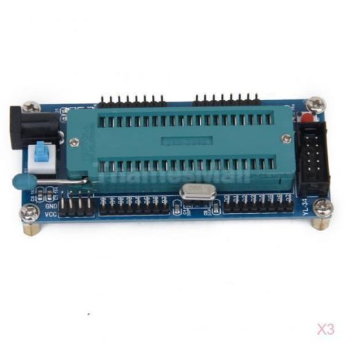
3x ISP ATMEGA16 ATmega32 Mini System Board AVR Minimum System Development Board
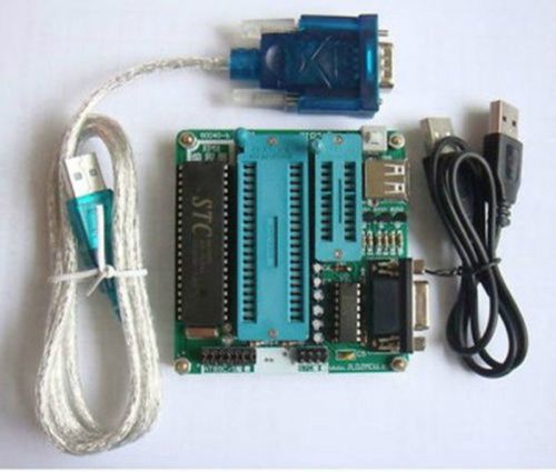
New 51 MCU Ep51 Microcontroller Programmer Writer AT89 STC Series + USB Cable
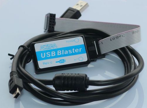
1Pcs New altera Mini USB Blaster Cable For CPLD/FPGA Download Line Best
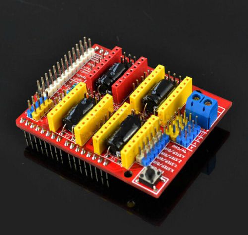
1Pcs New CNC Shield V3 A4988 Controller for RAMPS 1.4 Reprap 3D Printer Best
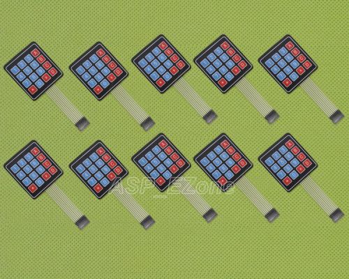
10pcs High Quality 4 x 4 Matrix Array 16 Key Membrane Switch Keypad Keyboard
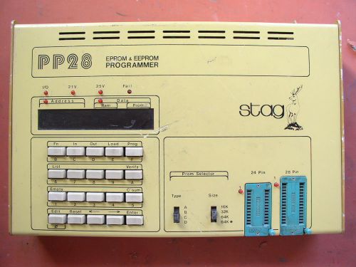
Vintage Stag PP28 Eprom & EEprom Programmer
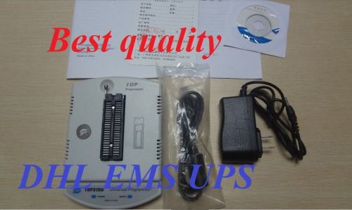
TOP3100 universal programmer with PLCC20, PLCC28, PLCC32, PLCC44, IC Extractor
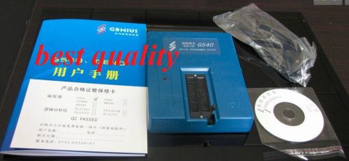
Genius G540 USB universal Bios GAL programmer with 4 pcs adapters G 540
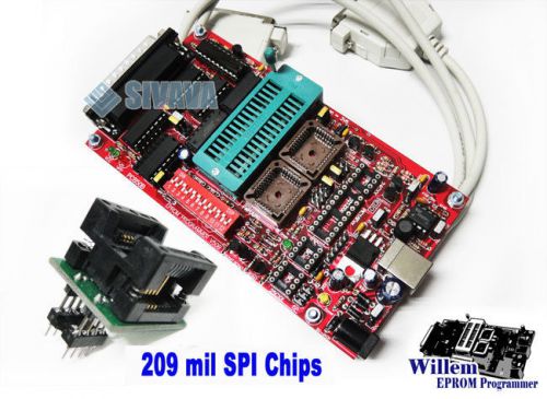
SIVAVA Willem EPROM Programmer PCB50B Universal + SOIC8 209mil to DIP8 Adapter
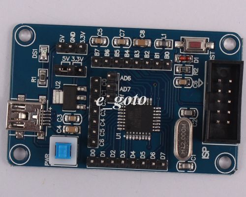
AVR ATmega168 8MHz Minimum System Development Board SPI Interface Good
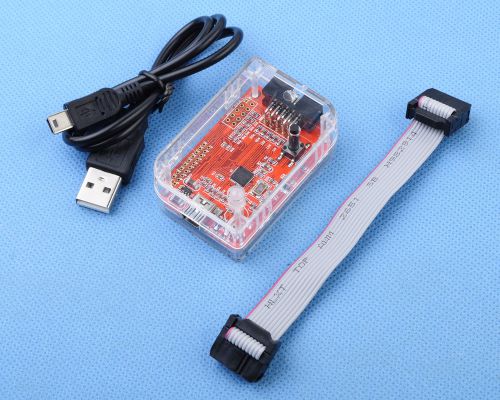
NEW CC Debugger and Programmer for RF System-on-Chips
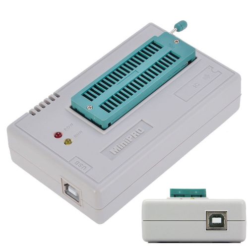
USB MiniPro TL866CS Universal Programmer Support All BIOS Multifunctional
MSP430 Programmer Parallel Debugger JTAG Emulator + 1M Cable
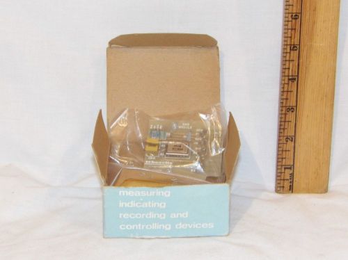
SMS Module Schaevitz Engineering 05171070-000, New in the Box, NOS
People who viewed this item also vieved
RELIANCE 0-52861 GATE DRIVER MODULE USED
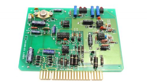
Atlas 09-3110-05 Rev.4 Weatherization machine Circuit Board- New!
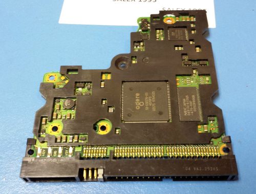
MAXTOR D740X-6L PCB Hard Drive IDE Logic Controller Board
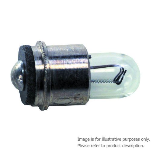
1 X Packof 10 MULTICOMP 6839-10PK LAMP INCANDESCENT SUB-MIDGET FLANGED 28V 672MW
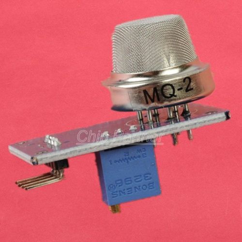
MQ2 MQ-2 Smoke methane Gas LPG Butane Hydrogen Gas Sensor Detector Module
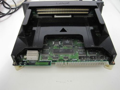
PCB JAMMA NEO GEO MVS MOTHERBOARD MV A1

NEW Merkury Innovations Mossy Oak Break-Up infinity Camo Power Bank 2200mAh

"Rayovac Recharge Plus Nimh Batteries, C, 2 Per Pack"
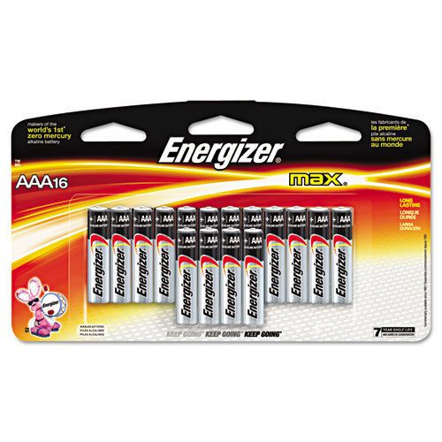
"Energizer Max Alkaline Batteries, Aaa, 16 Batteries/pack"
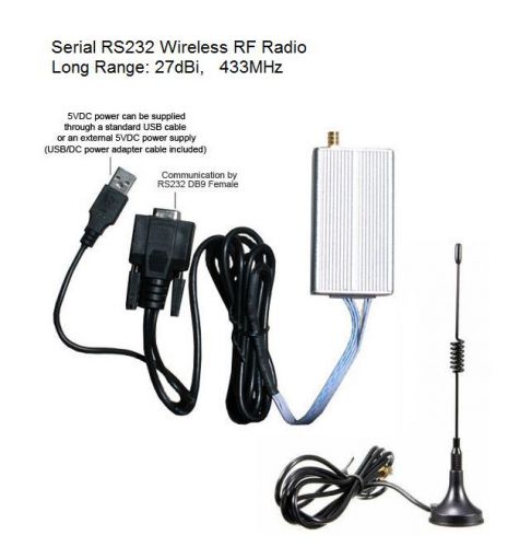
Serial RS232 Wireless RF Radio Data Modem, Long Range 9800ft Tranceiver 433MHz
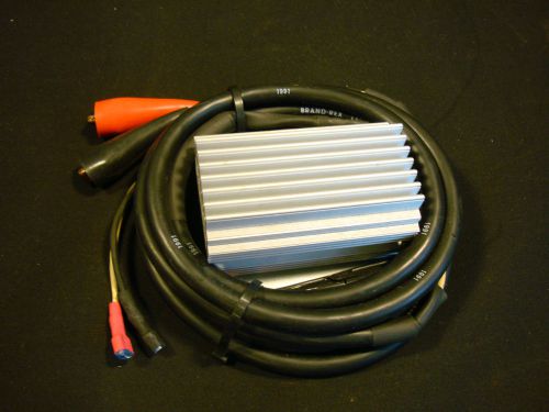
TRANSLECTRIC SM2412-5 HEAVY DUTY VOLTAGE CONVERTER 5A AMP 18-50V-DC TO 13.8Vdc
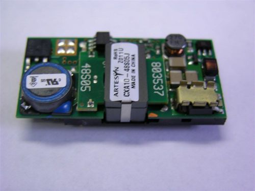
1 Artesyn CXA10-48S05J 18-75Vdc in 5V 2A 10W Out Open Frame DC-DC Converter
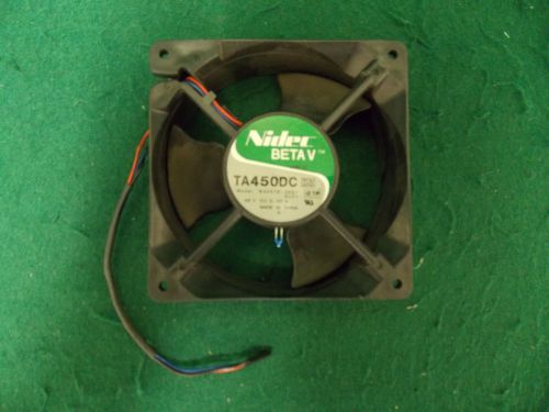
Nidec Cooling Fan BETA V TA450DC 3-Blade B34578-26G1 #
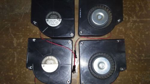
LOT OF 4- COMAIR ROTRON BD12B3 12v BISCUIT FAN, 2 PIN 25 CFM
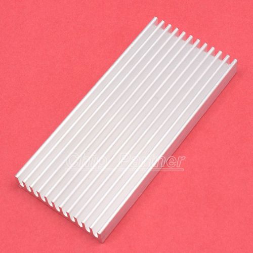
Heat sink 100*45*10MM IC Aluminum 100X45X10MM Cooling Fin
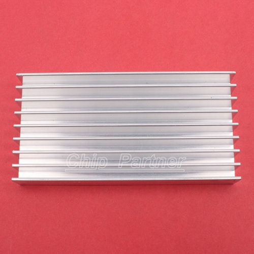
Heat sink 100*50*17MM IC Aluminum 100X50X17MM Cooling Fin
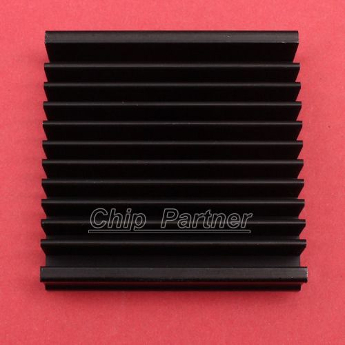
Heat sink 50*50*12.8MM IC Aluminum 50X50X12.8MM Cooling Fin
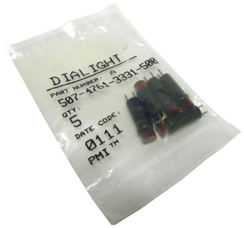
NEW DIALIGHT 507-4761-3331-500 5 PIECE RED INDICATOR LAMP
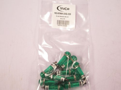
LOT OF 10 YC-9TRM-22G-220 9MM LED PILOT LIGHT 220V AC/DC TERMINAL RING+NUT
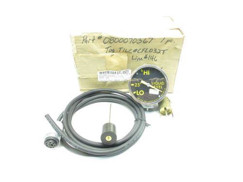
NEW QUALITROL DAL-042-35 LIQUID LEVEL FLOW INDICATOR D513059
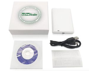
SZiTW Reader UHF USB Desktop Reader Writer with 860-960MHz Frequency Complies

Handheld 125Khz RFID ID Card Copier Reader Writer Entry Door Lock Access Control
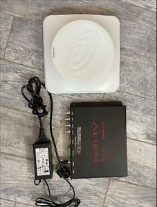
NO RESERVE - UHF RFID Reader & Antenna Alien ALR-9680 & 6dBi 62 deg
By clicking "Accept All Cookies", you agree to the storing of cookies on your device to enhance site navigation, analyze site usage, and assist in our marketing efforts.
Accept All Cookies