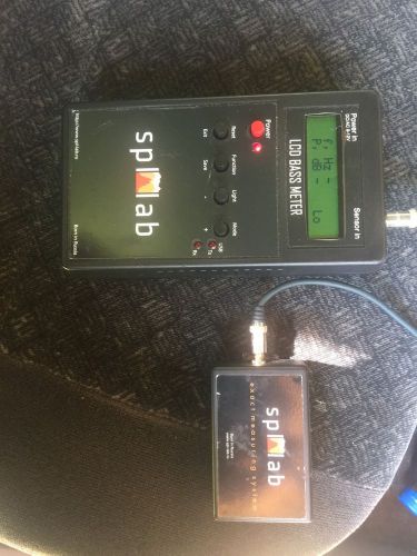
US $1300
Directions
Similar products from Sound Pressure Testers & Sound Level Meters
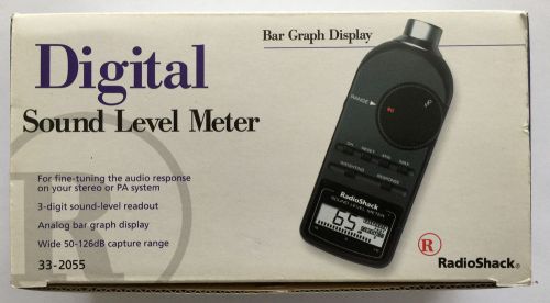
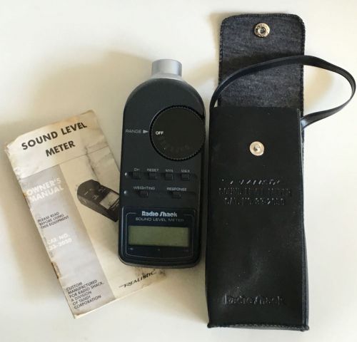
Audio Digital Sound Level Meter Model 33-2055 Radio Shack w/Case Box & Manual
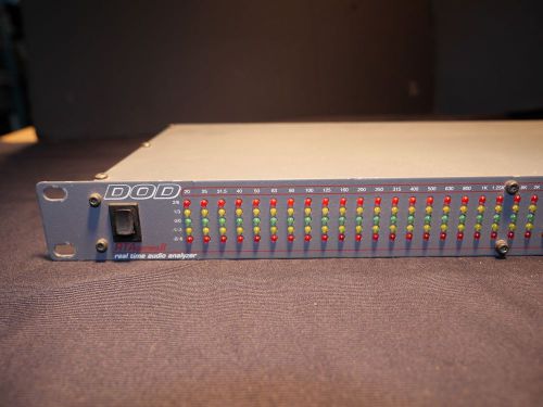
DOD RTA series II real time audio analyzer
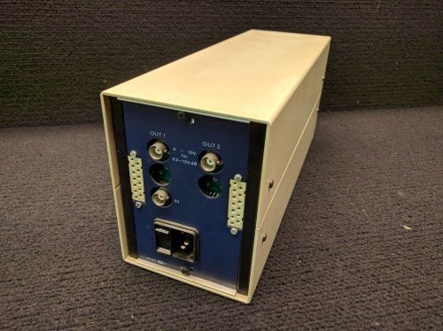
AVL Combustion Noise Meter 4050-A01
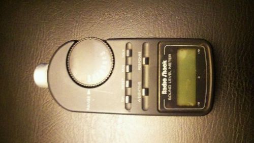
Radio shack db sound level meter
Radio Shack Realistic Sound Level Meter
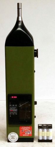
GENERAL RADIO GENRAD 1982 PRECISION LEVEL SOUND METER & ANALYZER
USA SELLER Ono Sokki Precision Integrating Sound Level Meter LA-500 w/ hard case
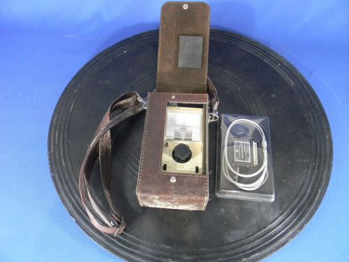
General Radio (GR) 1565-A, 44 to 140 dB, Sound Level Meter + Case & Microphone
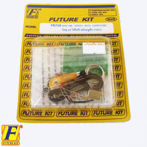
EARPHONE 3VDC Simple Basic MINI AM RADIO electrical circuit board kit DIY
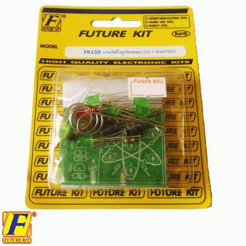
ATOMIC CHASING LIGHT 7 LED STUDENT ELECTRONIC LEARNING CIRCUIT BOARD UN AS
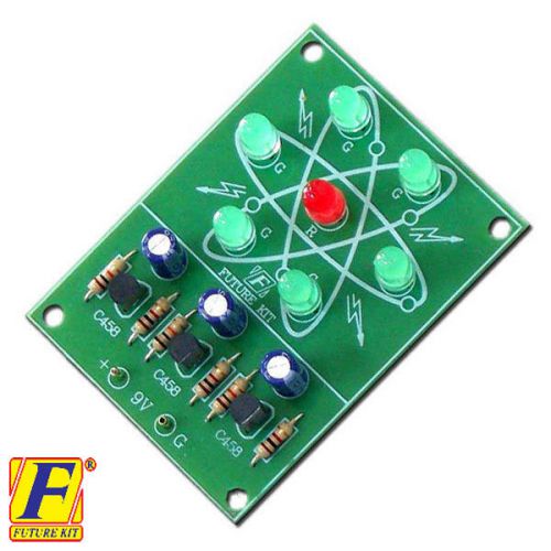
ATOMIC CHASING LIGHT 7 LED STUDENT ELECTRONIC LEARNING CIRCUIT BOARD ASSEM
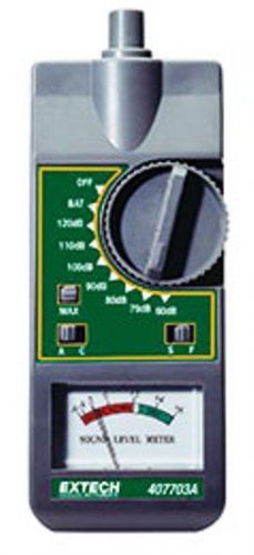
EXTECH ANALOG SOUND LEVEL METER 407703 NEW
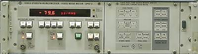
Rohde & Schwarz UPSF2 video noise meter
Cirrus CRL221C Type 2 Sound Level Meter
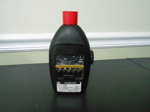
GenRad Permissable Sound Level Meter 1565-B
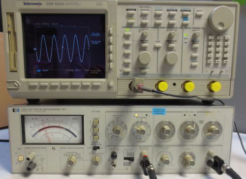
HP/Agilent 339A Distortion Measurement Test Set
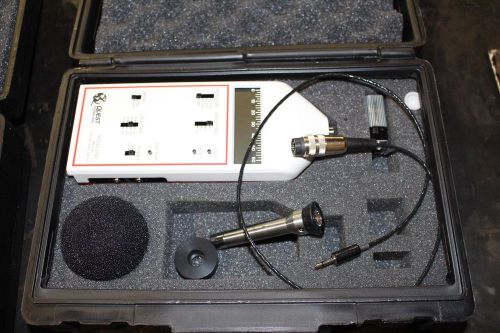
Quest Model 2700 Impulse Sound Level Meter
People who viewed this item also vieved

Lot of 13 Fiber Optic Attenuators OFATP-SC-UPC 15dB
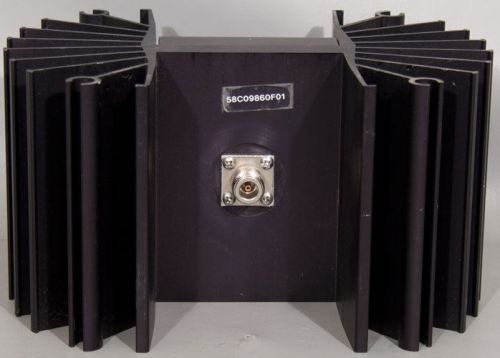
58C09860F01 50 Ohm 250W RF Dummy Load/Termination

OPTICAL LENS LOT 4 EA LASER OPTICS #2-101-2

GETTYS 14-0038-03 PC BOARD *USED*

LGP TELECOM LGP11225 CURRENT INJECTOR, OUTDOOR, CIN OD 890-960 MHz

HP 5345A Electronic Counter Circuit Card Assembly 05345-60007
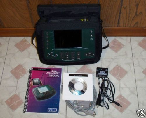
BIRD SA-2500A SITE ANALYZER 2.5GHz W/HARDCASE & ACCES!
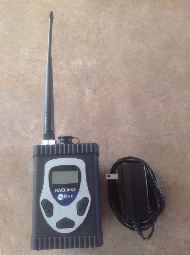
RAE RAELink 3 RLM3000 Wireless Bluetooth Integrated GPS Weatherproof MODEM ONLY

FLUKE 51 K/J Digital Thermometer Listed for charity

Tektronix 2235 Osciolloscope Original Operators Manual, Great conditio
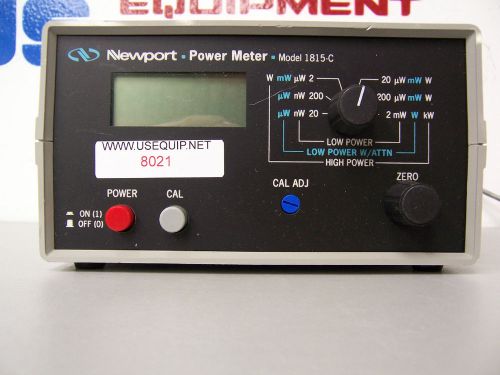
8021 NEWPORT 1815-C POWER METER
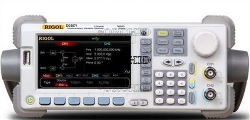
NEW RIGOL DG5071 FUNCTION/ARBITRARY WAVEFORM GENERATOR 70MHZ 1GSA/S 14 BITS

Ublox NEO-6M GPS Module w/Supporter for Pixhawk PX4 Flight Controller e

HP Agilent 10041A 100MHz 10X Mini Scope Passive Probe, with Hock, Ground Clip

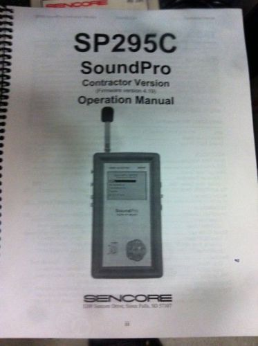
Sencore Audio Calibration Suite
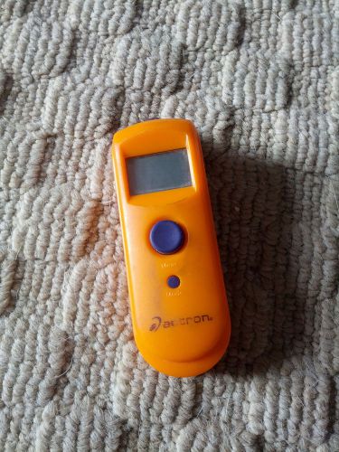
Actron CP7875 Pocket Thermometer / Non-contact IR temperature sensor

Datum 9310-611 Time Code Generator / Translator
Fisherbrand Disposable Glass Culture Tube 450 Ct Blood Test Lab Science Specimen

COMTECH CDM-720 / CDM-720L SATELLITE MODEM
By clicking "Accept All Cookies", you agree to the storing of cookies on your device to enhance site navigation, analyze site usage, and assist in our marketing efforts.
Accept All Cookies