US $640
Directions
Similar products from Motor Speed Regulators & Controllers

E-Bro PWM 12V-40V DC Electric Pump/Motor Speed Controller Stepless 10 -100 10A

Danfoss Cycletrol "150".. __150300 DC DRIVE 120VAC 1/8-1HP
MINARIK MM23001C DC MOTOR SPEED CONTROLLER 11-2269

Mini DC 5A Motor PWM Speed Controller 3V-35V Speed Control Switch LED Dimmer new
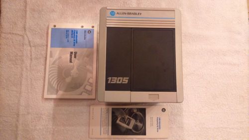
*NEW IN BOX* ALLEN BRADLEY 1305-BA06A ser. C AC Adjustable Frequency Drive 3 HP

NEW HENGSTLER ENCODER 0 524 557


FAN MOTOR SPEED CONTROL SWITCH (LT-30) 3A-120VAC (IN BOX)


Electronic Motor Control DC or Universal-7.5 Amps
assembled DC Motor Speed Control HHO PWM electronic circuit PCB board kit DIY

DANFOSS 2336 512F-2-Y58 POWER CUBE MODULE

SIEMENS, 3RW4047-1BB04, 55kW, 106A, SOFTSTARTER, NEW

TOSHIBA, Transistor invertor, VFS15-4055PL-W 5,5 kW, AC Servodriver.

ALLEN-BRADLEY POWERFLEX 4 DRIVE 22A-B1P5N104 SER.A 0-230VAC 1.8A 0.2KW/0.25HP

SIEMENS ,CPU315-2DP,6ES7 315-2AG10 -0AB0

dayton 5 Amp Speed Control 4X599

Fimco Variable Motor Speed Control VSC-10 12 Volt

Allen Bradley PowerFlex 525 Encoder Module 25-ENC-1 Brand New

New Penta Power KB Motor Speed Control KBIC-240 230 VAC
People who viewed this item also vieved

Eaton Cutlerhammer Motor Starter AN16DNO27 Amp 600 Volt

Definite Purpose Control Contactor 35 Amp Class 8910 Type DPA23

PAIR 1 POLE CONTACTOR 200A 18/30V type 2526 made in France

Eaton XTCEXTLA400 Contactor Accessory Terminal Lug Assembly 400A

Allen-Bradley Contactor 100-A38ND3 new

143447 New In Box, Eaton 9-2876-36 Contactor Coil, 24VAC@50/60HZ, NEMA Size: 0

143443 New-No Box, Siemens CRL0F4322K6ZPC Reversing Contactor 30A 600V Coil: 120

Square D Overload Relay Thermal Unit CC74.6 *Lot of 3* Used

Square D Overload Relay Thermal Unit B8.20 *Lot of 3* Used

GE Heater Element C356A *Lot of 3* Used

Square D Overload Relay Thermal Unit B1.03 *Lot of 3* New Surplus

Square D Overload Relay Thermal Unit B6.90 *Lot of 3* Used

Allen-Bradley Starter 709-DOD103 Series K, Size 3, 3 Phase, 3 Pole

Square D Overload Relay Thermal Unit B62 *Lot of 3* Used
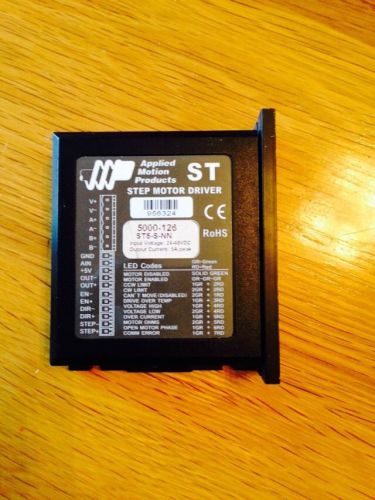
USED Applied Motion Products ST Step Motor Driver 5000-126 ST5-S-NN
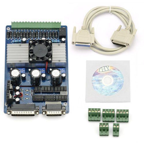
TB6560 3 Axis CNC 3.5A Stepper Motor Driver Controller Board NEW USA Source
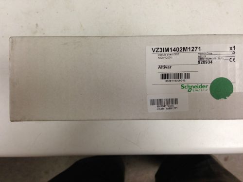
Schneider Electric Altivar Power IGBT Module - VZ3IM1402M1271
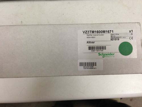
Schneider Electric Altivar Rectifier Module Thyristor - VZ3TM1600M1671
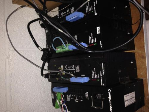
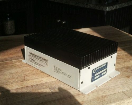
Parker Compumotor S8 Microstep Drive
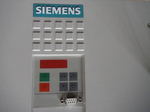
SIEMENS MASTER DRIVES VECTOR CONTROL 6SE70,6SE71
By clicking "Accept All Cookies", you agree to the storing of cookies on your device to enhance site navigation, analyze site usage, and assist in our marketing efforts.
Accept All Cookies