US $395.00
| Condition: |
New: A brand-new, unused, unopened, undamaged item in its original packaging (where packaging is
applicable). Packaging should be the same as what is found in a retail store, unless the item is handmade or was packaged by the manufacturer in non-retail packaging, such as an unprinted box or plastic bag. See the seller's listing for full details.
...
|
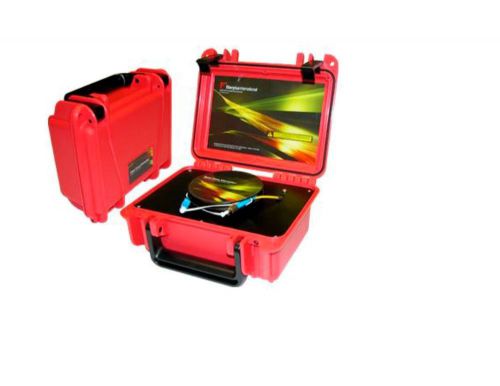
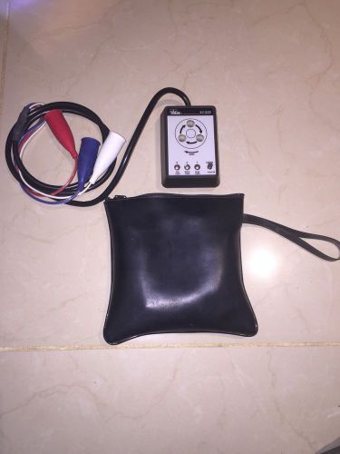
Brand | Fiber Plus International |
| MPN | 2121802 | ||
| Model | D5353-S5000 |
Directions
Similar products from Cable Fault Locators, Stress Test Sets & Power Sensors
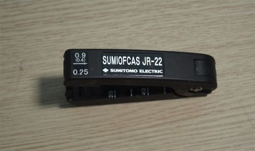
SUMIOFCAS JR 22 Optical Stripper
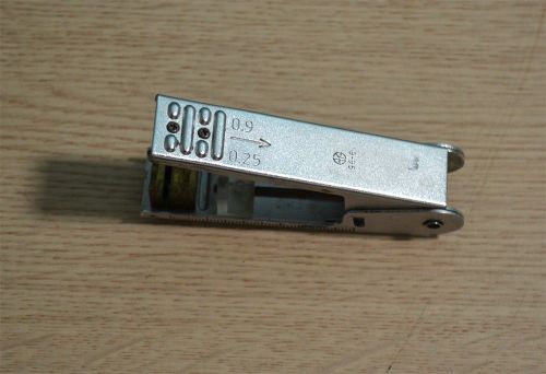
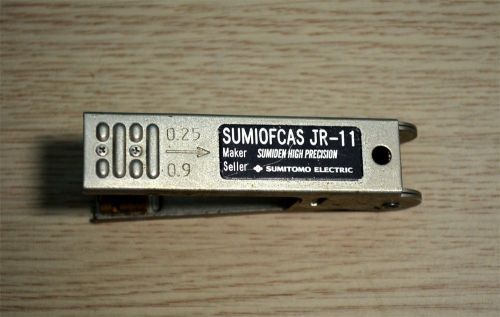
SUMIFOCAS JR 11 Optical Stripper
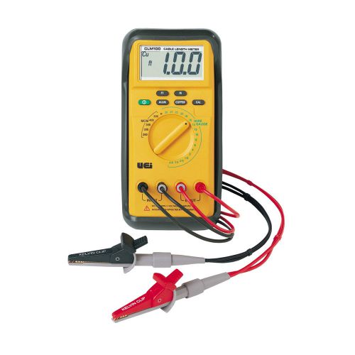
UEi Instrument CLM100 Cable Length Meter
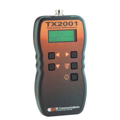
BI Communications TX2001 Graphical TDR Cable Fault Locator
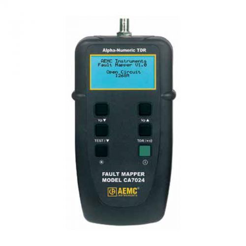
AEMC CA7024 FaultMapper Cable Fault Locator
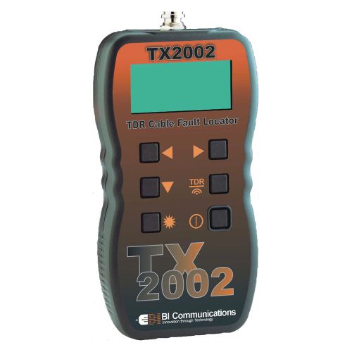
BI Communications TX2002 Graphical TDR Cable Fault Locator
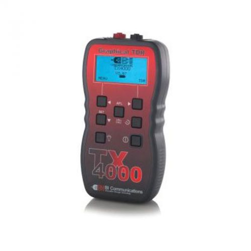
BI Communications TX4000 TDR Cable Fault Locator
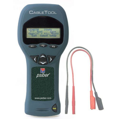
Psiber CT50 CableTool Multifunction Cable Length Meter
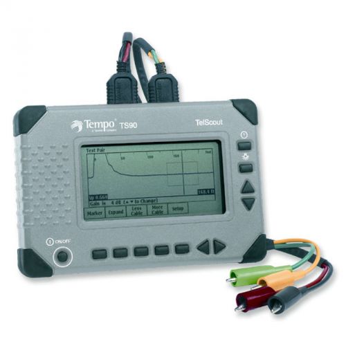
Tempo TelScout TS90US Cable Fault Locator TDR
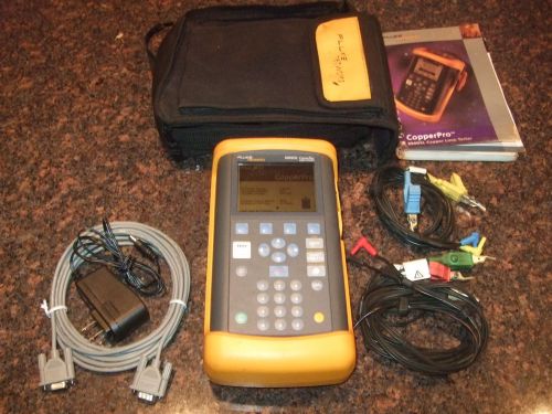
FLUKE NETWORKS 990DSL COPPERPRO TESTER WIDEBAND TDR CABLE DSL TESTER RFL 3.20.05
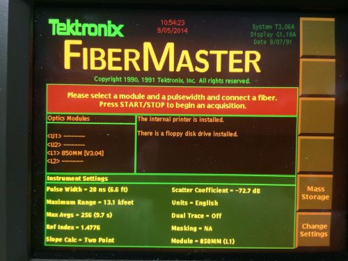
Tektronix TFP2 FiberMaster with Options 11 , 16 , 24 , 850nm MM OTDR Optics Mod
FLUKE NETWORKS 990DSL COPPERPRO DUAL CARRYING CASE
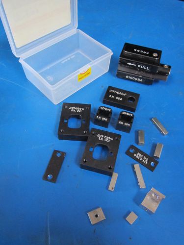
Lot of Jeff Industries & HP 81000BA Optical Test Parts
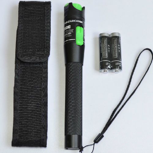
20Km Fiber Optic Cable Tester Fiber Optic Test Pen, 20mw, Premium quality
10Km Fiber Optic Cable Tester Fiber Optic Test Pen 10mw Premium quality
Digital Portable Palm OTDR Tester RY-OT2000 15/16dB 1310nm/1550nm +20nm
EXFO AXS-200/635i Copper VDSL VDSL2 ADSL ADSL2 + Sharp Tester AXS 200 635i 635
Battery Pack for GN NetTest CMA-series OTDRs
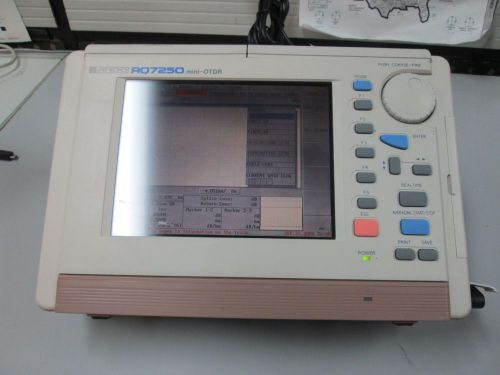
Ando AQ7250 Fiber Mini OTDR aq-7250 aq 7250
People who viewed this item also vieved
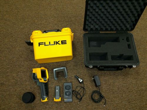
Fluke Ti32 320 x 240 60 hz Infrared - Thermal Camera
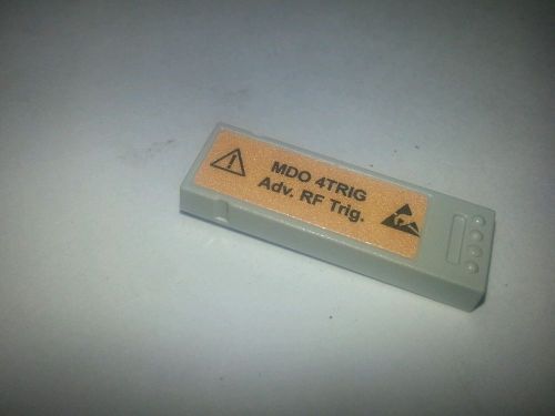
Tektronix MDO 4 TRIG Adv RF Trig Module
Ideal Phase Rotation Tester 61-520. Phase Sequence Tester.
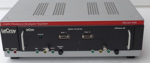
LeCroy CATC Protocol Analyzer System 10K PE401MG
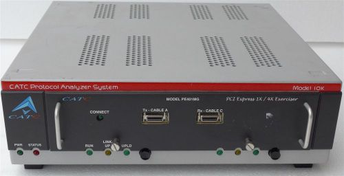
CATC Protocol Analyzer System 10K PE401MG (LeCroy)
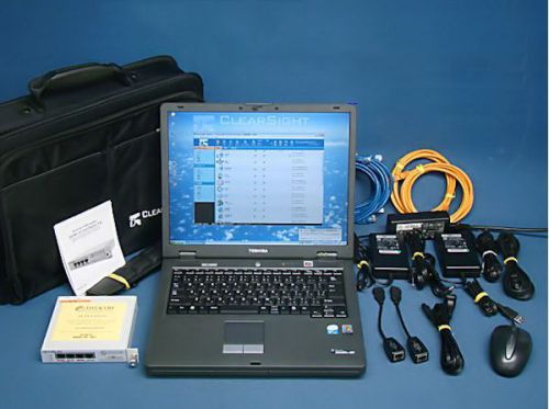
CLEAR SIGHT 10/100M Ethernet CSA-1107
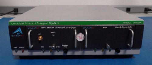
CATC 2500H Universal Protocol Analyzer System with BT004MA Bluetooth Plug-in
Agilent/HP 608B VHF Signal Generator Instruction Operating Manual/schematic 685-
Agilent/HP 608B VHF Signal Generator Instruction Operating Manual/schematic 307-
Agilent/HP 608A & 608B VHF Signal Generators Operation and Service Manual/sc(s)
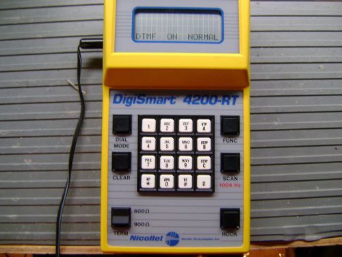
Nicolet Digismart 4200-RT trunk tester
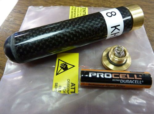
RYCOM INSTRUMENTS 001-00281-03 8 kHz Pipe Locator Sonde Transmitter, 3/4" NEW
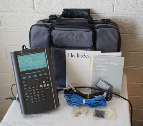
Fluke Networks 682 Enterprise LANMeter Ethernet Cat5e Network Analyzer
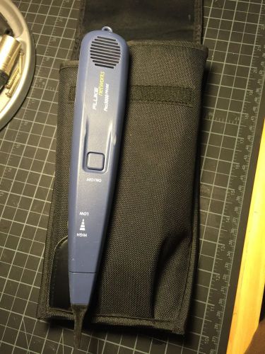
Fluke Networks Pro3000 With Case
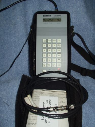
Sadelco MiniMax Signal Level CATV Meter
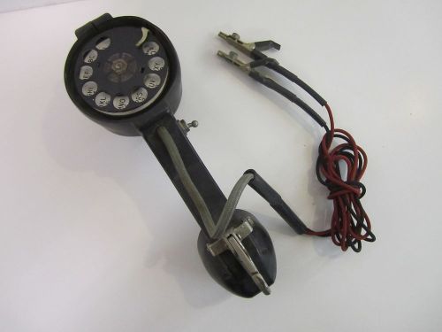
Vintage BECO Butt Set Linesman Test Set Telephone Rotary Dial Phone
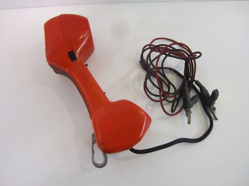
Harris Dracon TS21 TS 21 Lineman's Test Set Telephone Phone Line Tester Red
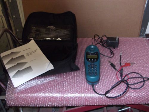
Harris TS250 Basic Rate ISDN Test Set with case, booklet
Harris Dracon Lineman's Telephone Test Set Phone Line Tester x410 Butt Set
By clicking "Accept All Cookies", you agree to the storing of cookies on your device to enhance site navigation, analyze site usage, and assist in our marketing efforts.
Accept All Cookies