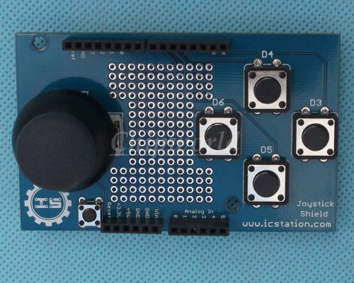
Recommendations For You 20% Off, $1.59 Now 50% Off, $3.00 Now 20% Off, $3.60 Now 50% Off, $2.65 Now 50% Off, $5.46 Now Visit my eBay Store:ChipWorld Product Name: NEW ICSJ011A Gamepads Joystick Shield for Arduino Simulated Mouse And Keyboard More Items In Our Store,Click Here! SKU: 4121 Parsts No. : Package: Brand: Quantity: 1 1 Channel Relay 2 Channel Relay 3 Channel Relay 4 Channel Relay 6 Channel Relay 8 Channel Relay Description: The joystick shield provides simple analog inputs along with four separate buttons and one button under the joystick itself. The joystick can be used for controlling outputs such as a melody or pixels on a screen. The buttons can be used for navigation or game control How do I find the current position of the joystick? The position of the joystick is calculated from the two potentiometers in the joystick. The joystick can move in two dimensions which typically would represent X and Y coordinates but could represent any two dimensional quantity. To read the potentiometers we use the analogRead() function which returns a number from 0 to 1023. We need to supply an analog pin number to the function—for the joystick shield the X position is read from analog pin 0 and the Y position is read from analog pin 1: Serial.println(analogRead(0)); // Prints current X position Serial.println(analogRead(1)); // Prints current Y position It is a good technique—because it clarifies your intent—to use ''constants'' for values that will not change when your sketch runs. With this in mind, the following sketch snippet sets up constants for the analog pins used and prints the current X and Y positions to the serial console: const byte PIN_ANALOG_X = 0; const byte PIN_ANALOG_Y = 1; void setup() { Serial.begin(9600); } void loop() { Serial.print("x:"); Serial.print(analogRead(PIN_ANALOG_X)); Serial.print(" "); Serial.print("y:"); Serial.print(analogRead(PIN_ANALOG_Y)); Serial.print(" "); Serial.println(); } How do I find the current direction of the joystick? It can be useful to use the value of the X and Y position to determine if the joystick is centered or moved in one of 8 directions (i.e. up, right-up, right, right-down, down, left-down, left, left-up). Since we know the value in each dimension will be between 0 and 1023 you might expect the centre value to be around 511 or 512 but because the joysticks are physical devices the actual value is unlikely to be that exact. If we choose the wrong value we'll find thatour joystick will be detected as moving in a particular direction even though it is centered. To work around this issue we specify two "threshold" values and consider that any value within that range should be considered "centered": |----------|----|----------| 0 505 515 1023 The threshold values you choose may be different depending on your joystick. We specify the values as constants in the code: const int X_THRESHOLD_LOW = 505; const int X_THRESHOLD_HIGH = 515; const int Y_THRESHOLD_LOW = 500; const int Y_THRESHOLD_HIGH = 510; Next, we want to map our value in each dimension from a position range of 0 to 1023 to a direction value in the range -1 to 1. For the X dimension -1 means moved to the left, 0 means not moved in the X dimension and 1 means moved to the right. For the Y dimension -1 means moved down, 0 means not moved in the Y dimension and 1 means moved up. We start by setting the direction in each dimension to 0 ("centered") and then we use if/else statements to check if the position value in either dimension is above or below our threshold values: x_direction = 0; y_direction = 0; x_position = analogRead(PIN_ANALOG_X); y_position = analogRead(PIN_ANALOG_Y); if (x_position > X_THRESHOLD_HIGH) { x_direction = 1; } else if (x_position < X_THRESHOLD_LOW) { x_direction = -1; } if (y_position > Y_THRESHOLD_HIGH) { y_direction = 1; } else if (y_position < Y_THRESHOLD_LOW) { y_direction = -1; } The Arduino provides a map() function which in theory we could use instead of if/ else but the method is complicated by the centering issues so we won't consider that approach here. As you can see in the next complete example we then use if/ else statements to print the direction—you can modify this example to perform whatever action you need: const byte PIN_ANALOG_X = 0; const byte PIN_ANALOG_Y = 1; const int X_THRESHOLD_LOW = 505; const int X_THRESHOLD_HIGH = 515; const int Y_THRESHOLD_LOW = 500; const int Y_THRESHOLD_HIGH = 510; int x_position; int y_position; int x_direction; int y_direction; void setup() { Serial.begin(9600); } void loop () { x_direction = 0; y_direction = 0; x_position = analogRead(PIN_ANALOG_X); y_position = analogRead(PIN_ANALOG_Y); if (x_position > X_THRESHOLD_HIGH) { x_direction = 1; } else if (x_position < X_THRESHOLD_LOW) { x_direction = -1; } if (y_position > Y_THRESHOLD_HIGH) { y_direction = 1; } else if (y_position < Y_THRESHOLD_LOW) { y_direction = -1; } if (x_direction == -1) { if (y_direction == -1) { Serial.println("left-down"); } else if (y_direction == 0) { Serial.println("left"); } else { // y_direction == 1 Serial.println("left-up"); } } else if (x_direction == 0) { if (y_direction == -1) { Serial.println("down"); } else if (y_direction == 0) { Serial.println("centered"); } else { // y_direction == 1 Serial.println("up"); } } else { // x_direction == 1 if (y_direction == -1) { Serial.println("right-down"); } else if (y_direction == 0) { Serial.println("right"); } else { // y_direction == 1 Serial.println("right-up"); } } How do I set up the Arduino so I can know when a button has been pushed on the Joystick Shield? Before you can know if a button on the shield has been pushed you need to set up your Arduino to recognize the buttons. Unsurprisingly you will perform this setup in the... setup() function! First we define constants for the Arduino pin associated with each button: // Select button is triggered when joystick is pressed const byte PIN_BUTTON_SELECT = 2; const byte PIN_BUTTON_RIGHT = 3; const byte PIN_BUTTON_UP = 4; const byte PIN_BUTTON_DOWN = 5; const byte PIN_BUTTON_LEFT = 6; If you've used a pushbutton switch before you may have noticed a resistor is normally required in order to detect a known voltage when the button is not pressed. To reduce the number of parts required this shield has been designed not to require resistors on the shield itself. Are you thinking to yourself "if push buttons require resistors and the shield has no resistors how can we get the shield to work?"? If you're not thinking that then you can probably skip reading this bit. (And if you're thinking "I'm really hungry" it might be time to put down the electronics and get some food.) It turns out your Arduino actually has internal resistors connected to the pins inside the microcontroller. In order to use the internal resistors we need to "enable the internal pull-up resistors". If that sounds to you like "hoist the jib and unfurl the main stay" then I can explain some more: When a "pull-up" resistor is connected to a push button it means that the voltage level when the button is not pressed will be HIGH because the resistors "pulls the voltage level up" to HIGH when the button is not pressed. On a typical Arduino a pin that is HIGH will be at 5 volts. When the push button is pressed the pin will read as LOW because there is less resistance between the pin and ground than there is between the pin and 5 volts. To enable a pin's pull-up resistor you first set the pin as an input and then enable the pull-up: pinMode(PIN_BUTTON_RIGHT, INPUT); digitalWrite(PIN_BUTTON_RIGHT, HIGH); The actual code to enable the pull-up doesn't really make any sense if you read it literally but that's the way it works. Other than remembering that an unpressed button will read as HIGH with a pull-up resistor and a pressed button will read as LOW you don't need to remember or understand the other details. In order to configure each pin to be an input and enable the pull up resistors we use the following code: void setup() { pinMode(PIN_BUTTON_RIGHT, INPUT); digitalWrite(PIN_BUTTON_RIGHT, HIGH); pinMode(PIN_BUTTON_LEFT, INPUT); digitalWrite(PIN_BUTTON_LEFT, HIGH); pinMode(PIN_BUTTON_UP, INPUT); digitalWrite(PIN_BUTTON_UP, HIGH); pinMode(PIN_BUTTON_DOWN, INPUT); digitalWrite(PIN_BUTTON_DOWN, HIGH); pinMode(PIN_BUTTON_SELECT, INPUT); digitalWrite(PIN_BUTTON_SELECT, HIGH); } See the next section to learn how to read whether a button is pressed or not. How do I know when a button on the Joystick Shield has been pressed? Once you have set up your Arduino to recognize the buttons (see above) you can tell whether the button is pressed with the digitalRead() function. When the value read is LOW the button is pressed and when the value is HIGH the button is not pressed. if (digitalRead(PIN_BUTTON_LEFT) == LOW) { // Button is pressed } else { // Button is not pressed } The following complete example will print the state of each button and the value of the joystick to the Arduino serial console: // Store the Arduino pin associated with each input // Select button is triggered when joystick is pressed const byte PIN_BUTTON_SELECT = 2; const byte PIN_BUTTON_RIGHT = 3; const byte PIN_BUTTON_UP = 4; const byte PIN_BUTTON_DOWN = 5; const byte PIN_BUTTON_LEFT = 6; const byte PIN_ANALOG_X = 0; const byte PIN_ANALOG_Y = 1; void setup() { Serial.begin(9600); pinMode(PIN_BUTTON_RIGHT, INPUT); digitalWrite(PIN_BUTTON_RIGHT, HIGH); pinMode(PIN_BUTTON_LEFT, INPUT); digitalWrite(PIN_BUTTON_LEFT, HIGH); pinMode(PIN_BUTTON_UP, INPUT); digitalWrite(PIN_BUTTON_UP, HIGH); pinMode(PIN_BUTTON_DOWN, INPUT); digitalWrite(PIN_BUTTON_DOWN, HIGH); pinMode(PIN_BUTTON_SELECT, INPUT); digitalWrite(PIN_BUTTON_SELECT, HIGH); } void loop() { Serial.print("l:"); Serial.print(digitalRead(PIN_BUTTON_LEFT)); Serial.print(" "); Serial.print("r:"); Serial.print(digitalRead(PIN_BUTTON_RIGHT)); Serial.print(" "); Serial.print("u:"); Serial.print(digitalRead(PIN_BUTTON_UP)); Serial.print(" "); Serial.print("d:"); Serial.print(digitalRead(PIN_BUTTON_DOWN)); Serial.print(" "); Serial.print("x:"); Serial.print(analogRead(PIN_ANALOG_X)); Serial.print(" "); Serial.print("y:"); Serial.print(analogRead(PIN_ANALOG_Y)); Serial.print(" "); Serial.print("s:"); Serial.print(digitalRead(PIN_BUTTON_SELECT)); Serial.print(" "); Serial.println(); } Material Download For more quantity, please contact me.(My skype: ada-yu2013) The Standard shipping we provide is non-regiested mail without a tracking. We provide free shipping with tracking number when your order is over $50. If your oder is below $50 and you need tracking, please contact me. Maybe you request 2pcs 2.4GHz NRF24L01+ Antenna Wireless Transceiver Module For Microcontrol new 4pcs 433Mhz WL RF transmitter and receiver link kit for Arduino/ARM/MCU 20pcs 433Mhz WL RF transmitter and receiver link kit for Arduino/ARM/MCU good 5pcs new Breadboard 830 Point Solderless PCB Bread Board MB-102 MB102 Test DIY 9PCS NEW TEC1-12706 Thermoelectric Cooler Peltier 12V 60W 92Wmax good $ 3.8 + free shipping $ 6.0 + free shipping $ 28.0 + free shipping $18.0 +free shipping $ 28.0 + free shipping Any problem, please contact us freely 1) We accept PayPal payment ONLY. inkFrog Analytics
By clicking "Accept All Cookies", you agree to the storing of cookies on your device to enhance site navigation, analyze site usage, and assist in our marketing efforts.


![Yaskawa ETP613491 PCB Inverter Board [PZO]](/_content/items/images/17/4830117/001.jpg)
![Yaskawa ETC740025 PCB Inverter Board [PZO]](/_content/items/images/18/4830118/001.jpg)
![Yaskawa ETP6U3022 PCB Inverter Board [PZO]](/_content/items/images/19/4830119/001.jpg)

![[10x] RFID IC Key Tags Keyfobs Token NFC TAG Keychain Mifare 13.56MHz Arduino](/_content/items/images/88/4938388/001.jpg)