C $34.79
| Condition: |
New: A brand-new, unused, unopened, undamaged item in its original packaging (where packaging is
applicable). Packaging should be the same as what is found in a retail store, unless the item was packaged by the manufacturer in non-retail packaging, such as an unprinted box or plastic bag. See the seller's listing for full details.
...
|
Brand | Undisclosed |
| MPN | Does not apply |
Directions
Similar products from Inductance, Capacitance, Resistance and Impendace Meters & Analyzers
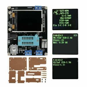
TFT LCD GM328 TRANSISTOR TESTER, DIODE LCR ESR METER,PWM,SQUARE WAVE GENERATOR

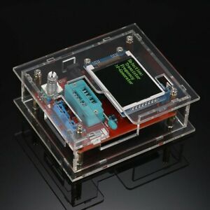
TFT LCD GM328 Transistor Tester Diode LCR ESR Meter PWM Square Wave Generator
SainSmart Mini Digital Tweezers Intelligent SMD Tester Portable LCR Meter Diode
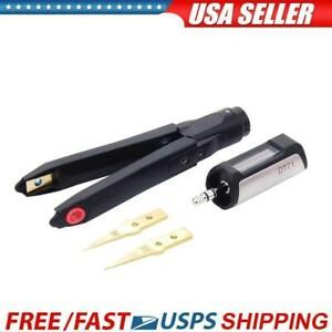
DT71 Portable Digital Mini Tweezers LCR Meter Signal Generator Repair Tool
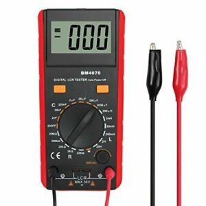
LCR Meter Capacitance Inductance Resistance Tester Multimeter Self Red
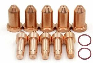
770791 Electrode & 770797 Tip/Nozzle 40A for Hobart Airforce 40i Plasma Cutter X
Keysight Used E4982A LCR Meter 1 MHz to 3 GHz, Options: 300,019

LCR-TC1 Transistor Tester ESR Capacitance Meter Electronic E PNP Component Z5W1

Parts Transistor Tester Replacement TFT LCD GM328 Accessories DIY Useful
HP / Agilent 4284A Precision LCR Meter 20 Hz - 1 MHz
1.8 Inch TFT LCD M328 Transistor Tester Diode Triode Checker Capacitance Meter M

Geekcreit® LCR-T3 LCR-T4 Mega328 Transistor Tester Diode Triode Capacitance ESR
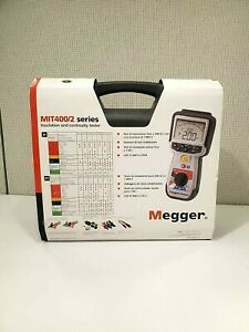
Megger MIT420/2 -Brand New Unit in Box - NEW Condition!

Hioki 9268-01 DC Bias Voltage Unit Untested Defective AS-IS For Parts
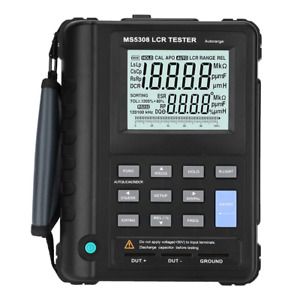
Akozon LCR Meter MS5308 Portable Handheld 100Khz Inductance Resistance Capacitan
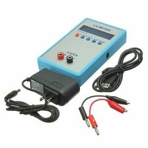
LC200A Digital L/C Handheld Inductance Capacitance Multimeter

BSIDE ESR02PRO Digital Transistor SMD Components Tester Diode Triode Capacitance
Sanwa Electric Instrument LCR meter LCR700

ESI Primary Standard SR104, SR 104 10KOhm Resistor IN CASE
Hewlett Packard 4291A Hi Temp, Hi Impedance Test Head, GOOD!!
People who viewed this item also vieved
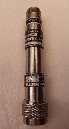
WEINSCHEL 50-30 COAXIAL ATTENUATOR N(M/F) 526

MICROSCOPE OBJECTIVE OPTICS 45X LEITZ WETZLAR GERMANY #2-147

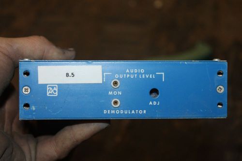
Alloy EP-6 IDS-PC 100188 Rev G PC Board
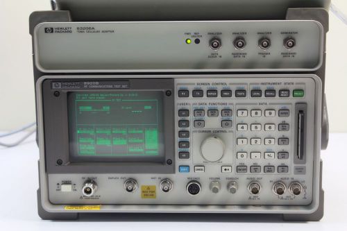
HP 8920B W/ 83206A RF COMMUNICATION TEST SET W/ OPT. 001,004,013,051,800
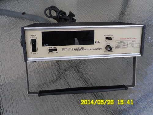
TAKEDA RIKEN TR5143 FREQUENCY COUNTER MODEL 5243
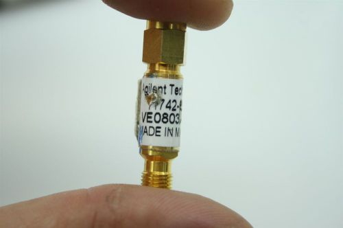
HP/Agilent 11742A Blocking Capacitor 0.045 to 26.5 GHz Malaysia Made

DRAGER CMS PERMISSIBLE GAS ANALYZER (NOT WORKING)
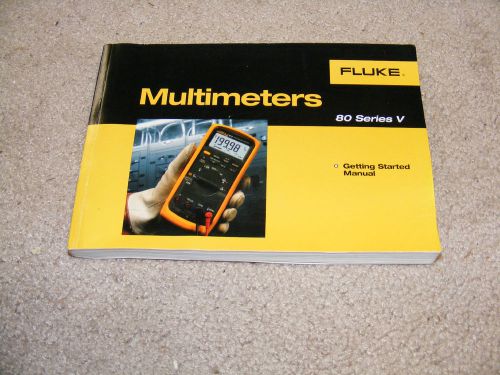
(1) FLUKE MULTIMETER MANUAL 80 SERIES "USED" IN VERY GOOD SHAPE
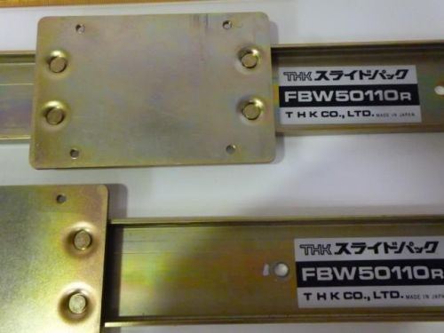
THK Positioning Rails FBW50110R, 600L, Length: About 21” L422
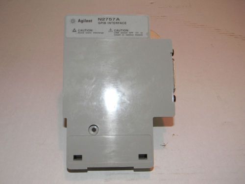
Agilent HP N2757A GPIB Interface Module - Minor Cosmetic Issue - Good Operation
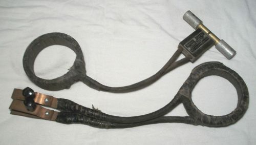
2 Antique General Electric Current Adapter Transformer Winding Ring Old School
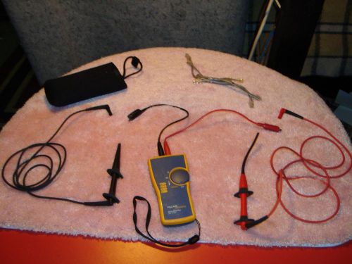
FLUKE NETWORKS INTELLITONE PRO 200 TONER DIGITAL CABLE ANALYZER
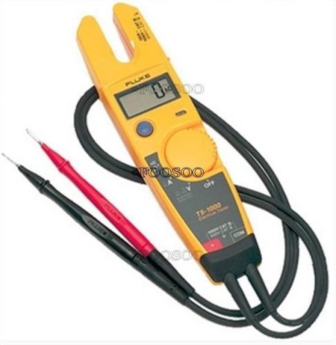
CONTINUITY CURRENT GAUGE MEASURE CLAMP BRAND NEW FLUKE T5-600 ELECTRICAL TESTER
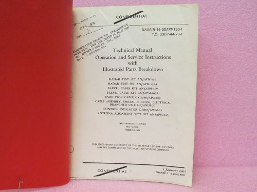
Military Manual AN/APM-130, AN/APM-130A Radar Test Sets Oper., Serv. IPB Manual

SNC AP123-WM Humzapper Induction Neutralizing & TEN Transformer w/Wiring
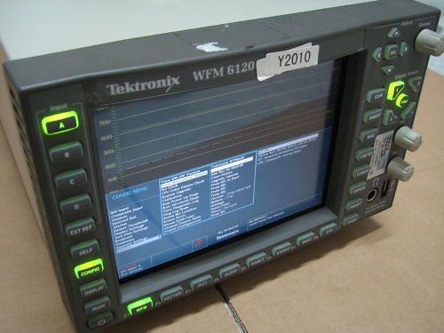
TEKTRONIX WFM6120 SD WAVEFORM MONITOR
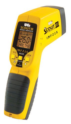
UEI INF215 Scout 3 IR Thermometer
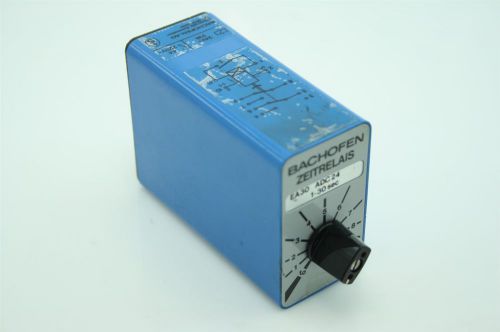
Bachofen EA30 ADC24 1-30 Sec Programmable Multifunction Time Relay CH-8610

VACUUM TUBE SYLVANIA 3DZ4 RECEIVER TV HAM RADIO BIN#D6
By clicking "Accept All Cookies", you agree to the storing of cookies on your device to enhance site navigation, analyze site usage, and assist in our marketing efforts.
Accept All Cookies