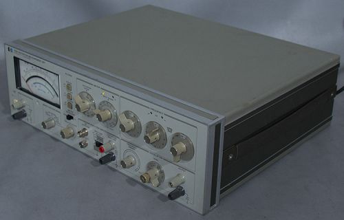
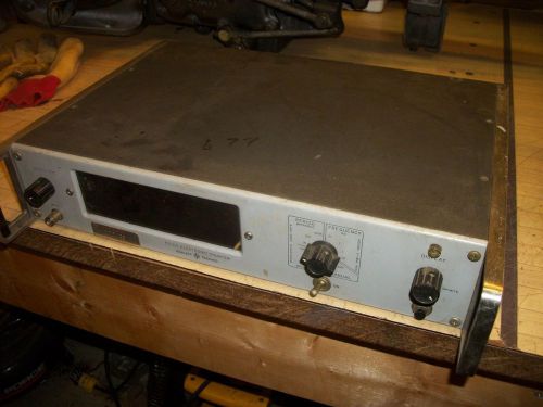
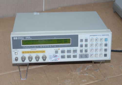
Hewlett Packard/Agilent 339A Distortion Measurement Test Set w/Opt. 001 Comes with what you see in the pictures. If you don't see it, you probably wont get it. Specifications are from and may vary slightly due to upgrades, options, or revisions this unit may or may not have. This set is guaranteed to work for 30-days, parts and labor, excluding freight. Link to the Manual: HP/Agilent 339A Distortion Test Set Manual Link to the Manual: HP/Agilent 339A with Option 001 Distortion Test Set Manual Description: An HP 339A with Option 001 installed is a standard 339A Distortion Measurement Set with two additional voltmeter input ranges. These ranges are .3 mV and .1 mV full scale. Measurement capabilities are from .1 mV rms full scale to .3 mV rms full scale in a frequency range of 10 Hz to 80 kHz, and from .001 V rms full scale to 300 V rms full sclae in a frequency range of 10 Hz to 110 kHz. When switched to the .3 mV range, the voltmeter attenuator is set to 0 dB. When switched to the .1 mV range, the voltmeter attenuator remains at 0 dB and 10 dB of gain is added to the input amplifier. This gives the required input for full scale deflection on the front panel voltmeter. These changes in voltmeter range have been accomplished by adding two additional positions on S4 of the Analyzer/Power Supply printed circuit assembly. Distortion Specifications: Fundamental Frequency Range: 10 Hz to 110 kHz continuous frequency coverage in 4 decade ranges with 2-digit resolution. Distortion analyzer and oscillator are simultaneously tuned. Distortion Measurement Range: 0.01% full scale to 100% full scale (-80 dB to 0 dB) in 9 ranges. Detection and Meter Indication: True rms detection for waveforms with crest factor < or = to 3. Meter reads dB and % THD (Total Harmonic Distortion). Meter response can be changed from NORMAL to VU ballistics with a front panel switch. Option 001 Specifications: Voltage Range: Standard: 1 mV rms full scale to 300 V rms full scale (-60 dB to +50 dB full scale, meter calibrated in dBV and dBm into 500 ohm). Option 001: .1 mV rms full scale to 300 V rms full scale (-80 dB to +50 dB full scale, meter calibrated in dBV and dBm into 600 ohm). Accuracy: Standard: @ INPUT RANGE .001 V to 300 V 20 Hz to 20 kHz: ±2% 10 Hz to 110 kHz: ±4% Internal Noise Floor: Option 001: 30 kHz Filter Setting, 6 µV Noise Level. 80 kHz Filter Setting, 8 µV Distortion Measurement Accuracy: 20 Hz to 20 kHz: ±1 dB 10 Hz to 50 kHz: +1, -2 dB 50 kHz to 110 kHz: +1.5, -4 dB Note: The above specifications apply for harmonics < 300 kHz. Fundamental Rejection: 10 Hz to 20 kHz: > 100 dB 20 kHz to 50 kHz: > 90 dB 50 kHz to 110 kHz: > 86 dB Distortion Introduced by Instrument (Input > 1 V rms): 10 Hz to 20 kHz: < -95 dB 20 kHz to 30 kHz: < -90 dB 30 kHz to 50 kHz: < -85 dB 50 to 110 kHz: < -70 dB Residual Noise (Fundamental frequency setting < 20 kHz, 80 kHz filter in, source resistance < or = to 1 kΩ shielded): < -92 dB referenced to 1 V. Input Level for Distortion Measurement: 30 mV to 300 V rms (100 mV range minimum) Input Impedance: 100 kΩ ±1.0% shunted by < 100 pF input High to Low. DC Isolation: Input low may be connected to chassis ground or floated 30 V to reduce the effects of ground loops on the measurement. Auto Set Level: No set level adjustment required. Distortion measurements are made directly over 10 dB range selected by input range switch. Two LED annunciators provide a fast visual indication to change input range for valid distortion measurement. Correct range is indicated when both annunciators are extinguished. Auto Null: Using Internal Oscillators: No manual frequency tuning necessary when using internal oscillator as signal source. Oscillator frequency controls simultaneously tune the analyzer. Using External Frequency Source: Two LED annunciators provide a quick visual indication for the operator to increase or decrease the analyzer frequency controls. When the analyzer is rough tuned to within one least significant digit of the fundamental frequency, the indicator lights are extinguished and the 339A auto-null circuitry takes over to provide a fast accurate null without tedious operator tuning. Input Filters (usable on all functions): Low Pass: 30 kHz - 3 dB point at 30 kHz, + 2.6 kHz, -3 kHz. Provides band limiting required by FCC for proof-of-performance broadcast testing. 80 kHz - 3 dB point at 80 kHz, +7 kHz, -7.9 kHz. Normally used with fundamental frequencies < 20 kHz to reduce the effect of higher frequency noise present in the measured signal. High Pass: 400 Hz - 3 dB point at 400 Hz, +35 Hz, -40 Hz. Normally used with fundamental frequencies > 1 kHz to reduce the effect of hum components in the input signal. Monitor Output: Provides scaled presentation of input signal after fundamental is removed for further analysis using oscilloscope or low frequency spectrum analyzer. Output Voltage: 1 V rms ±5% open circuit for full scale meter indication, proportional to meter deflection. Output Resistance: 1 kΩ ±5%. Voltmeter Specifications: Voltage Range: 1 mV rms full scale to 300 V rms full scale (-60 dB to +50 dB full scale, meter calibrated in dBV and dBm into 600 Ω) Frequency Range: 10 Hz to 110 kHz Accuracy (% of range setting): 20 Hz to 20 kHz: ±2% 10 Hz to 110 kHz: ±4% Detection and Meter Indication: True rms detection for waveforms with crest factor < or = to 3. Meter reads true rms volts, dB V, and dBm into 600 Ω Input Impedance: 100 kΩ ±1.0% shunted by < 100 pF Input High to Low. Monitor Output: Provides scaled presentation of input signal for further analysis using oscilloscope or low frequency spectrum analyzer. Output Voltage: 1 V rms ±5% open circuit for full scale meter indication, proportional to meter deflection. Output Resistance: 1 kΩ ±5%. Relative Input Level Specifications: Provides a ratio measurement relative to an operator selected reference level with readout directly in dB V or dBm (600 Ω). Voltage range, frequency range, accuracy specifications, and monitor are the same as in VOLTMETER mode. (Accuracy is relative to 0 dB set level input.). Oscillator Specifications: Frequency Range: 10 Hz to 110 kHz in 4 overlapping decade ranges with 2 digit resolution. Frequency vernier provides continuous frequency tuning between 2nd digit switch settings. Output Level: Variable from < 1 mV to > 3 V rms into 600 Ω with 10 dB/step LEVEL control and 10 dB VERNIER adjustment. OSC LEVEL position on function switch allows a quick check of oscillator level without disconnecting leads to device under test. OFF position on Oscillator LEVEL control provides fast signal-to-noise measurement capability. Oscillator output terminals remain terminated in 600 &Omega. Frequency Accuracy: ±2% of selected frequency (with FREQUENCY VERNIER in CAL position). Level Flatness: 20 Hz to 20 kHz: +0.1 dB 10 Hz to 110 kHz: ±0.2 dB Distortion (> or = to 600 Ω load, < or = to 3 V output): 10 Hz to 20 kHz: < -95 dB (0.0018%) THD 20 kHz to 30 kHz: < -85 dB (0.0056%) THD 30 kHz to 50 kHz: < -80 dB (0.01%) THD 50 kHz to 110 kHz: < -70 dB (0.032%) THD Output Resistance: 600 Ω ±5% AM Detector Specifications: Frequency Range: Carrier Frequencies: 550 kHz to 1.6 MHz Modulation Frequencies: 20 Hz to 20 kHz. Distortion Introduced by AM Detection (with 30 kHz filter switched IN): Up to 85% Modulation: < -36 dB (1.6%) THD 85% to 95% Modulation: < -30 dB (3%) THD Input Level: Maximum: 60 V peak Modulation Signal Level: 2.0 v rms minimum, 10 V rms maximum Monitor Output (with modulated RF carrier applied to AM Detector input): Distortion Mode: Provides scaled presentation of demodulated input signal after fundamental is removed. Voltmeter and Relative Input Mode: Provides scaled presentation of demodulated input signal. Note: Output Voltage and Output Resistance are the same in Distortion mode. General Specifications: Operating Environment: Temperature: 0°C to 50°C Humidity Range: < 95%, 0°C to 40°C. Storage Temperature: -40°C to +65°C. Power: 100/120/220/240, +5%, -10%, 40 to 66 Hz, 200 mA max. Weight: 8.2 kg. (18 lbs.) Dimensions: 426 mm W x 146 mm H x 442 mm D (16.75" x 5.75" x 17.4" D) For More Pictures Please Click the Following: Picture 2 - Front View Picture 3 - Back View Picture 4 - Right Side View Picture 5 - Left Side View Picture 6 - Serial Number Tag For Domestic Customers: Packaging, handling, and order processing included in shipping in all domestic shipments as quoted by the shipping calculator. For International Customers there is a $50.00 minimum for packaging, handling, and order processing. International shipping to be determined by destination. Prior to shipment I need to know the following information: (1) Are you the end-user of this item? (2) If you are not the ultimate end-user of the item, please state the ultimate end user's name. (3) What is the ultimate country destination? If you have any questions please call Michael at 1-866-MHZ-ELEC (1-866-649-3532) Toll Free. Also, please click here to view or other auctions! 04/01/16 Powered by eBay Turbo Lister The free listing tool. List your items fast and easy and manage your active items.
By clicking "Accept All Cookies", you agree to the storing of cookies on your device to enhance site navigation, analyze site usage, and assist in our marketing efforts.