US $130.00
Directions
Similar products from DC Power Supply Modules & Regulators
Applied LED Driver Power Supply Adapter AC 100-240V to DC 20-36V Waterproof 30W
Applied LED Driver Power Supply Adapter AC 100-240V to DC 20-38V Waterproof 70W
Applied LED Driver Power Supply Adapter AC 100-240V to DC 20-38V Waterproof 60W
8.4V/1A Power Supply Charger Adapter For Bike T6/P7 LED Light US Plug Applied
BERTAN ASSOCIATES HIGH VOLTAGE POWER SUPPLY 0-1000 VDC 15 MA MODEL 214
LAMBDA LNS-Z-6 REGULATED POWER SUPPLY
Sencore PS-43 Porta-Pak Universal Rechargeable Battery Power Supply
UNIVERSAL ELECTRONICS TRANSISTORIZED POWER SUPPLY 35VDC 15A MODEL LQ35-15A
Burglar Alarm Power Supply Transformer
FM3KV6 positive thin high voltage DC power supply multiplier
CM3KV2-3 negative cylinder high voltage DC power supply multiplier
CM3KV2-6 positive high voltage DC power supply 12 stage multiplier
FSP FSP 120-AAB AC/DC ROUND BARREL ADAPTER
DC 12V to 5V 3A Power Converter Module with Dual USB Output For Car Boat

E-C APPARATUS EC250-90 POWER SUPPLY / ELECTROPHORESIS (ec1)

IDEC PS5R-D24 Power Supply - 24 VDC - 50 Watt Output

NEW IN BOX Sorensen Programmable DC Power Supply DLM20-30M130

BK Precision Model 1670 DC Power Supply, Free Shipping
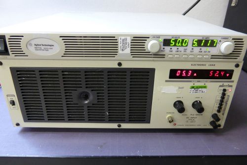
Agilent N5771A 0-300V 0-5A 1500W DC Power Supply LOAD TESTED Current model
People who viewed this item also vieved

Surge Suppressor EMC panel mount

Verifone I.T.E. Power Supply PS664422G 22VAC for Omni 3200 3300 07096-01G

Pelco MCS16-20E Master Power Supply 720W 120VAC 16 Outputs 480VA Total

Staticon STATIAC AC Voltage Regulator/Filter/Conditioner Type LC10B1960FPX

Condor Plug-In Class 2 Transformer 12VAC 35VA WP573512CG Case Lot of 30 New NOS

4PC Cisco PWR-850-870-WW1 Power Adaptor 857/871W/877/878

NEW Cisco AIR-PWR-SPLY1 AC Adapter Power Supply for Aironet 1250 1252 Series 56V

1PC Used CISCO POWER 341-0107-01 FOR WS-C3750G-48TS / WS-C3560G-48TS Switch

1PC Cisco PWR-3900-AC Cisco power supply for Cisco 3945 3925 have been tested

LH Research Tiny-MITE Power Supply TM34-13Y3Y1/115 115AC

NEW 110VAC DF1753-500 12V Load Pure Sine Wave Input Voltage Inverter 500W Dump

lot of 15, 6EF8, AC Power Entry Modules 6A IEC-WIRE LEAD FLANGE MOUNT

Phihong PSC30U-050 (S)-R Power Supply Adapter 100-240V/5V 4A 20W 2.1x5.5x10mm

Eico Grid Dip Meter Model 710 Vintage

W.M. Welch Scientific Co. AC & DC Power Unit// Model 2606B

PHC MODEL 512 REGULATED POWER SUPPLY Free Shipping!

Astec LPS55 Open Frame Power Supply 24V 2.5A 60W Output
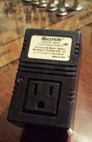
Recoton ADF50 iPhone Tablet Samsung Cell Phone Foreign Voltage Converter Outlet
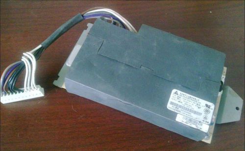
1PC DELTA Power Supply (DPSN-150BP A) for Cisco WS-C3550-48-SMI/EM 12T/12G
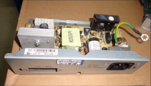
CISCO POWER for C3560-48/24TS WS-C2960-48/24TT-L WS-C2960-48/24TC (341-0097-02)
By clicking "Accept All Cookies", you agree to the storing of cookies on your device to enhance site navigation, analyze site usage, and assist in our marketing efforts.
Accept All Cookies