
US $2.89
| Condition: |
New: A brand-new, unused, unopened, undamaged item in its original packaging (where packaging is
applicable). Packaging should be the same as what is found in a retail store, unless the item is handmade or was packaged by the manufacturer in non-retail packaging, such as an unprinted box or plastic bag. See the seller's listing for full details.
...
|
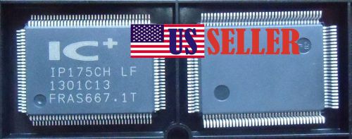
Brand | IC+ |
| MPN | IP175CH-LF | ||
| Model | IP175CH-LF QFP |
Directions
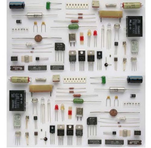
Similar products from Electrical Integrated Circuits & Processors
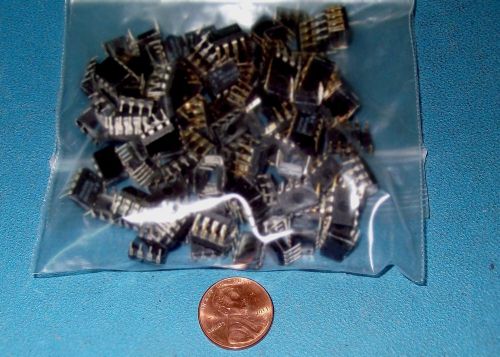
APPRX 200PC LOT CAT35C104 4K BIT SERIAL EEPROM - DIP8
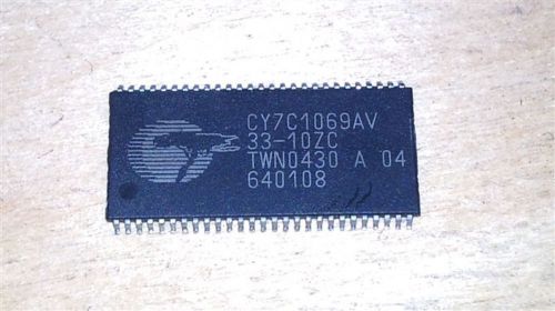
CY7C1069AV33-10ZC 2M BY 8 STANDARD SRAM, 10 ns, PDSO54 (10 PER)
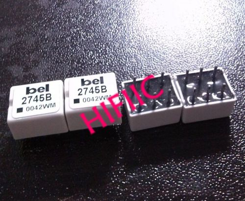
1PCS 2745B HIGH FREQUENCY MAGNETICS T1/E1 Through Hole Transformer DIP6
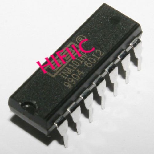
1PCS INA101HP High Accuracy INSTRUMENTATION AMPLIFIER DIP14
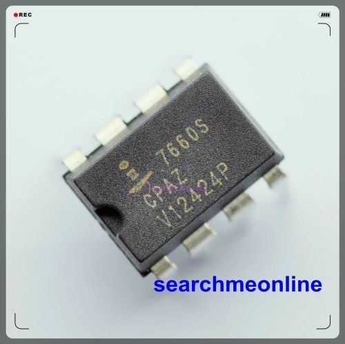
25pcs ICL7660SCPAZ ICL7660S Convert Voltage DIP-8 NEW
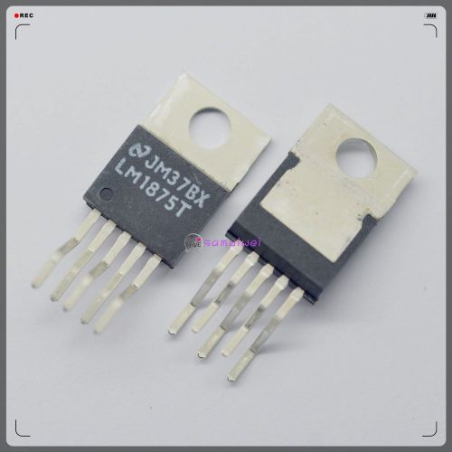
4pcs NEW 100%-ORIGINAL GENUINE NS LM1875T LM1875 Audio Fever Amplifier IC
70PCS Original 1N5822 3 Amp 40V Schottky Barrier Rectifier Diode DO-27
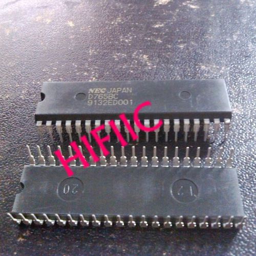
1PCS UPD765BC D765BC Single/Double Density Floppy-Disk Controller DIP40
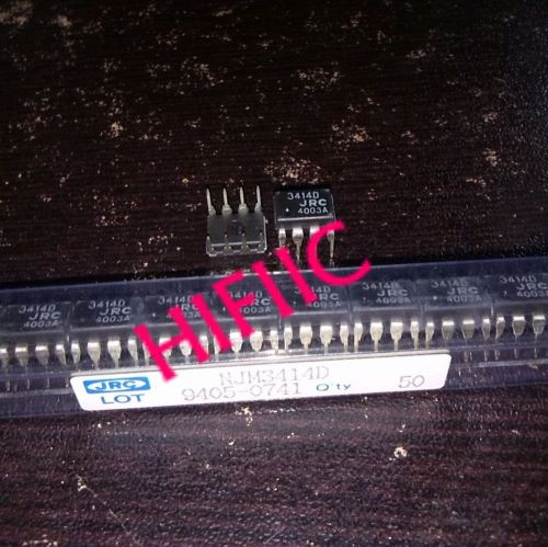
1PCS NJM3414D SINGLE-SUPPLY DUAL HIGH CURRENT OPERATIONAL AMPLIFIER DIP8
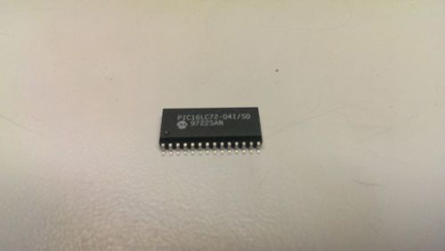
Lot of 100 pic16lc72-04 surface mount. pic microcontroller
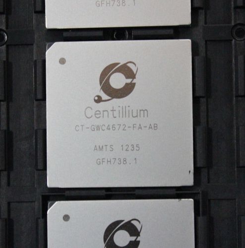
NEW CENTILLIUM VOIP CPU PROCESSOR IC CHIP CT-GWC4672-FA-AB (S17-3-28H)
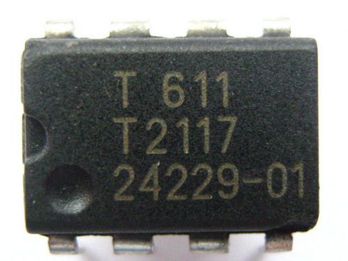
T2117-3ASY DIP8 Atmel Zero-voltage switch with adjustable ramp
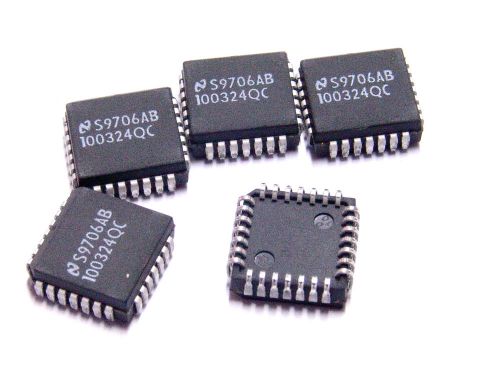
Lot of 5pcs NATIONAL 100324QC Low Power Hex TTL-to-ECL Translator 28-Pins PLCC
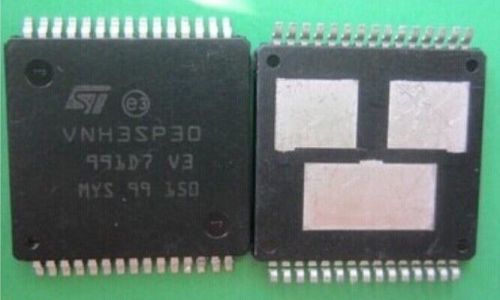
1PCS VNH3SP30 Automotive fully integrated H-bridge motor driver HSOP30
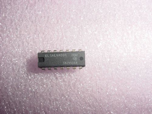
10 NEW SN7492AN ICs 14pins BINARY UP COUNTER
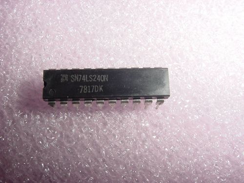
18 NEW SN74LS240N ICs 20pins BUFFR/LINE DRIVER
People who viewed this item also vieved
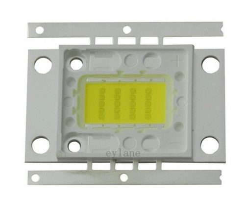
1pc High Quality 20W Cool White 20000k Super bright LED Lamp F
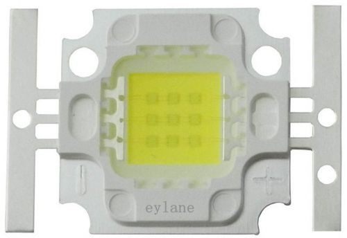
10x 10W 45mil Cool White 20000K High Power Brightest LED Lamp for Aquarium F
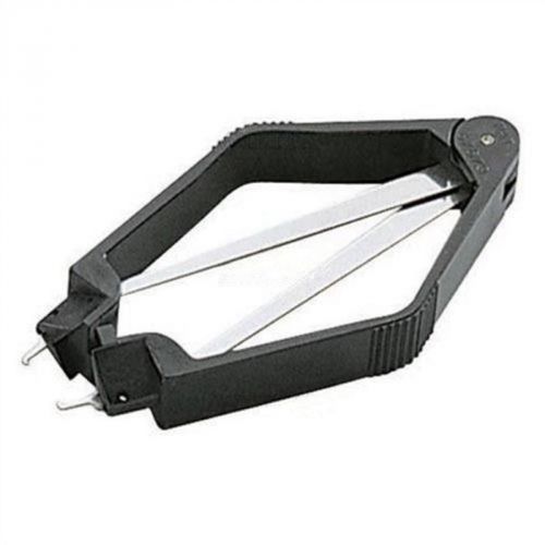
Brand New PLCC IC Chip Extractor Motherboard Circuit Board Component Puller Tool
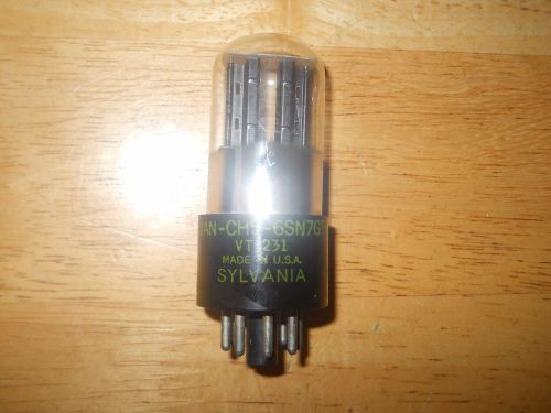
(1) Sylvania JAN-CHS-6SN7 GT VT-231 Radio Tube (2700 and 2375 Microhmos)
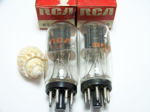
RARE MATCHED PAIR RCA 6SN7GTB 6SN7GT COIN BASE BLACK PT Vintage Amp Tube NOS NIB
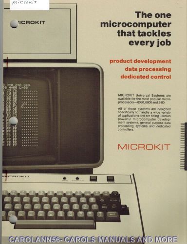
MICROKIT 3 Manuals FUTURE DATA, EXTENDED BASIC, SYSTEMS Reference
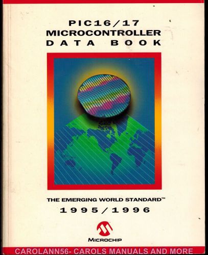
MICROCHIP Data Book 1995-96 Pic16-17 Microcontroller
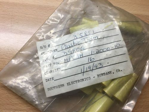
BRAND NEW SEC CAPACITOR .1UF 10% 3KVDC MODEL MPE11H ( 16 AVAILABLE)
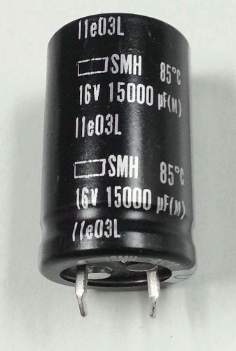
NEW Capacitor NIPPON 15000UF 16V 20% SNAP
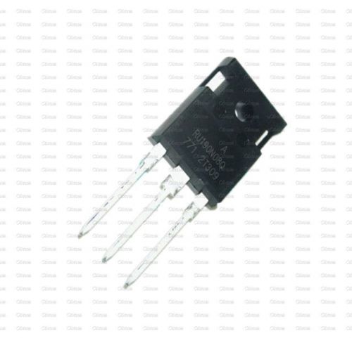
RU190N08 RU190N08Q N-Channel Advanced Power MOSFET IC
Transtector Systems, Inc. - TSJ Surge Protection, 48 VDC
(1PCS) MP1498DJ-LF-Z IC REG BUCK J 2A SYNC 1498 MP1498
(5PCS) MC79L05ACHX IC REG LDO -5V .1A SOT-89 79L05 MC79L05
By clicking "Accept All Cookies", you agree to the storing of cookies on your device to enhance site navigation, analyze site usage, and assist in our marketing efforts.
Accept All Cookies