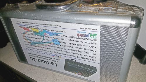
This is a brand new still sealed Janatek La-Gold-36 high performance logic analyzer with integrated pattern generator. Runs on Windows 98/ME/2000/XP/VISTA32 Product Information A logic analyzer with an integrated pattern generator. The LA-Gold-36 is a high performance logic analyzer with an integrated pattern generator. It was designed to be of superior technical quality to ensure measurements of excellent signal integrity. With class-leading specifications, it offers a comprehensive digital debugging environment for the electronics professional. The pattern generator is seamlessly integrated with the logic analyzer functionality. It can be used to stimulate the hardware that is being debugged, while the logic analyzer can actively await and capture the response. A maximum sampling rate of 1 GHz is available on all channels. The LA-Gold-36 has a large data buffer of 1 Mb samples per channel for sampling rates of up to 500 MHz on all 32 channels. The large buffer allows long capture times at high sampling rates. The digital logger function is for capturing very slow varying signals, e.g. room temperature. A Powerful Software Environment The software for the LA-Gold-36 is mature and both the logic analyzer and pattern generator are controlled from a single, intuitive user interface. The LA-Gold-36’s integrated pattern generator can be used in conjunction with the logic analyzer. The user can set up the instrument to output data to the unit under test (UUT) with the pattern generator and then measure its response with the logic analyzer. This, and other flexible triggering options for both the logic analyzer and pattern generator functions, makes the LA-Gold-36 a cut above the rest. Capture the Data that YOU want The flexible triggering options of the LA-Gold-36 make it possible to capture the exact data the user wants to view. Edge triggering may be set to occur on a rising edge, falling edge or change-of-state on any one or combination of channels. Pattern (level) conditions are set by specifying a ‘1’, ‘0’ or ‘X’ (don’t care) condition on all channels. Combinations such as Edge OR Pattern, Edge AND Pattern, Edge THEN Pattern, Pattern THEN Edge, etc. may be set. Pattern durations may be set to trigger when shorter (glitch capture), or longer than a specified period. A ‘post trigger delay’ function allows the final data capture to be postponed by an accurate time after trigger detection. An Integrated Pattern Generator The pattern generator, working in close combination with the logic analyzer, adds a new dimension to debugging possibilities. The outputs of the pattern generator can act as inputs to the unit under test. The response from the unit under test can then be used to trigger the logic analyzer. The 8-channel pattern generator can output data at rates up to 50 MHz. The output patterns can be specified to come from a user file or from the ’Pattern Editor’. The pattern generator can be started on various conditions, for example, start on a specific condition in the logic analyzer input signals, similar to a logic analyzer trigger condition. The parcel consist of the following: An Aluminum Carry Case La-Gold-36 Unit An USB-PC Cable 4 Sets of 8 x SMD Grabber Clips with ground leads Power Supply (Only for some laptops with limited current capabilities) Manual (Hardcopy) Software (CD-ROM) Specifications General Specifications Internal sampling rates: 1GHz down to 100Hz Digital inputs: 32 inputs, -60V to +60V, 1MO/5pF minimum input impedance, 100MHz input bandwidth Data buffer: 1Meg / 1048 000 (decimal) samples per channel up to 500MHz sampling rate 4k samples per channel for 1GHz sampling rate Pattern Generator: : Pattern source Pattern editor or user file Nr of channels 8 Data to output clock 50MHz max Minimum input impedance of load 4k7/100pF Modes of Operation Single/Continuous Connection to PC: USB 2.0 High Speed Mode (USB 1.1 Full Speed compatible) Trigger conditions : Pattern 1, 0, and dont care ("X") conditions selectable on all channels. Edge On any one or combination of channels. Rising edge, falling edge or change of state Edge/Pattern combinations Edge and pattern triggering may be combined for single captures or for conditionally continuous capture: Pattern, rising edge, falling edge, Change of state Pattern OR/AND/THEN rising/falling edge/Change of state. Rising edge/falling edge/Change of state OR/AND/THEN pattern Pattern < duration (glitch capture) Continuous Unconditionally: Display updates at regular intervals Conditionally: Display updates on detecting a trigger condition Mouse/Keyboard A trigger may be forced Threshold voltage: -5V to 5V Extended capture time: Dependant on the sampling rate. At 500MHz: 33ms max, At 1.25kHz: 1677s max Pre-/post-trigger buffer setting: The pre-/post-trigger buffer relation may be changed in 1000 samples steps. Software environment : Windows: Windows 98, ME, 2000, XP, Vista or later compatible versions. Run the LA-Gold-36 and the Unit Under Test in different windows simultaneously Ease of use The software is very easy to use. Most functions are directly selectable via a button bar on the main screen. Display : No. of channels Any number of channels may be displayed. Channel/group names User specified signal/group names Display order/Colors User specified Zooming Zoom in/out/previous/all/between cursors Single capture Captures a single set of data Continuous capture display Unconditionally: Continuously captures and displays data at a fixed update period. Conditionally: Updates the display each time a specified edge or pattern trigger condition is met. Cursors Various for time measurements, indicating the trigger point, etc. Time measurements The time differences between any two cursor lines or trigger line may be displayed. Take measurement easily by clicking mouse on first edge and on second edge to get the time difference. The time difference may also be indicated as a frequency. Edge snapping: Cursors (X, Y & Z) snap to signal edges for accurate time measurements. Pattern search: Any channel conditions may be searched for. 1, 0 and dont care conditions specified. Search from start/cursors, repeated search Printed output: The timing diagrams, bitmaps, binary and hex data, may be printed. Landscape and portrait. Power requirements: 3.6W Max capturing data, without pattern generator. 3.8W Max capturing data, with pattern generator The LA-Gold-36 will be fused with a 1.6A (or less) Resetable fuse External clock Synchronized capturing into linear/ring buffer. Linear capture start on trigger or immediately. Input to Ch31. More inputs may be defined in later software versions. clock on rising/falling edge, 50 MHz max. clock on rising/falling edge, 50 MHz max. Input Input to Ch31. More inputs may be defined in later software versions. Asynchronous clock on rising/falling edge, 50 MHz max. Synchronous clock on rising/falling edge, 50 MHz max. Unit dimensions/weight: 136mm x 122mm x 26mm, 260g
By clicking "Accept All Cookies", you agree to the storing of cookies on your device to enhance site navigation, analyze site usage, and assist in our marketing efforts.