US $1500
Directions
Similar products from Time Providers & Other Time Testing Equipment
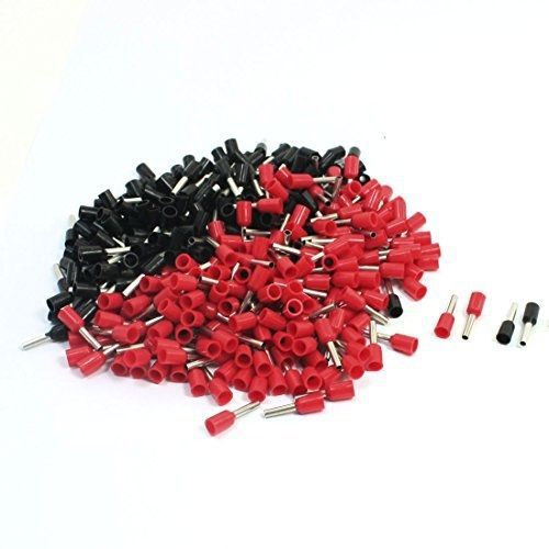
uxcell 16AWG Wire E1508 Pre Insulate Ferrules Terminals Red Black for 380Pcs
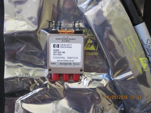
Hewlett Packard coaxial switch 8765A 4Ghz 24V
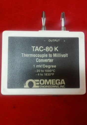
Omega TAC-80 k thermocouple to millivolt converter
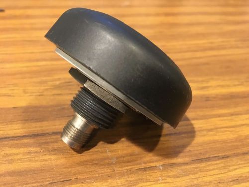
MAXRAD PCTEL 3978D Wi-Sys GPS Permanent Mount Antenna Ant TNC(F) 40dB 3-5V A
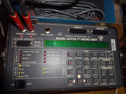
Phoenix Microsystems model 5575A T1 Micro Bet test set
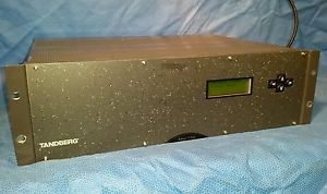
DVB Tandberg TT7000 SmurtMux Professional Multiplexer ASI
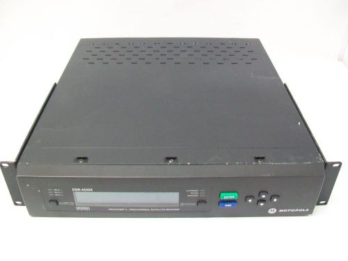
Motorola Digicipher II Professional Satellite Receiver DSR-4520X
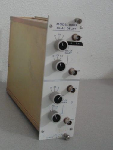
LASL 8003 Dual Delay NIM Module
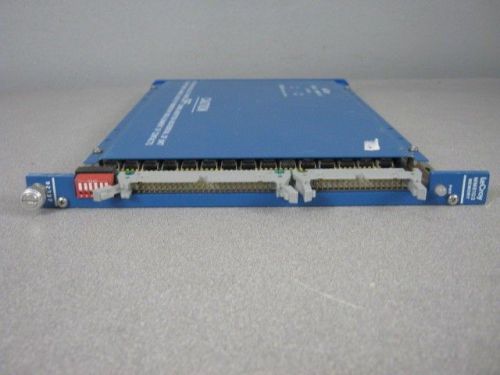
Lecroy MM8103 Memory Module CAMAC Crate
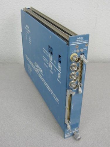
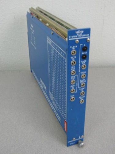
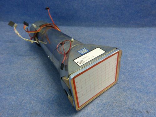
LeCroy TR 8818A Transient Recorder CAMAC Module
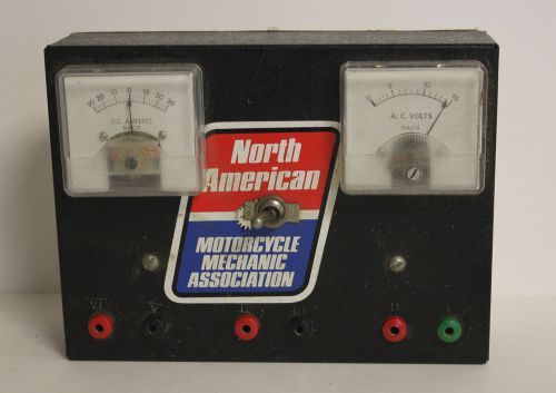
Vintage North American Motorcycle Mechanic Association Electric Tester Collector
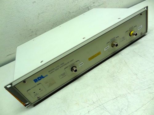
RDL INC. MODEL: CTS-1000 CATV TEST SYSTEM RF UNIT CTS-1000A *AMERICAN MADE*
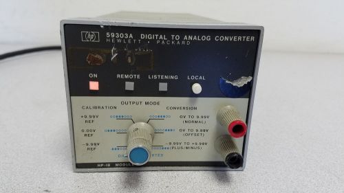
HP 59303A Digital to Analog Converter HP-IB
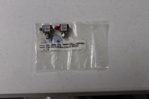
ALCATEL FILTER MODULE 51A2-04 355-0506-170 5.850-6.425GHz Qty. 2
JULIE RESEARCH LABORATORIES DMR-105 10K OHM STEP PRECISION RESISTANCE STANDARD
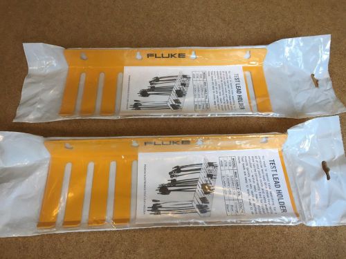
2 Pomona Fluke Test Lead Holder Racks 10 Slots New In Package Cord /Cable Holder
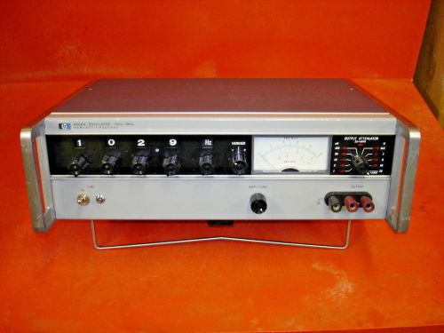
4204A Hewlett Packard Signal Generator
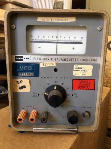
Kintel Electronic Galvanometer Model 204A - 10uv .001ua 10000 ohms (D5)
People who viewed this item also vieved
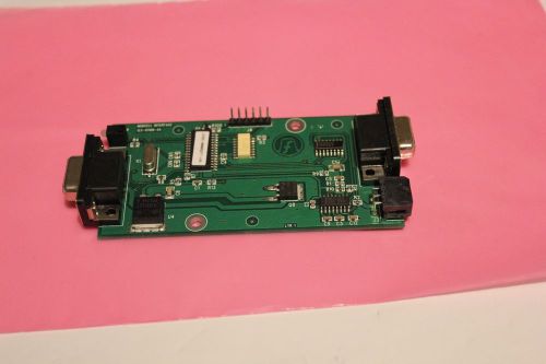
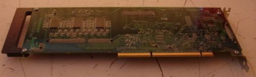
MODCELL INTERFACE BOARD 123-01108-XA (S6-3-4FE)
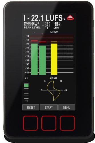
DK1 Compact Audio and Loudness Meter
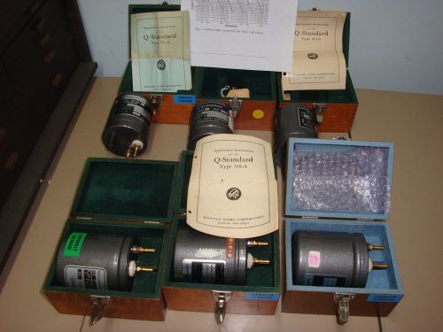
6) Boonton/HP 513-A5, 518-A4, 513-A, 518-A2, 518-A3, 518-A1 Q Standard
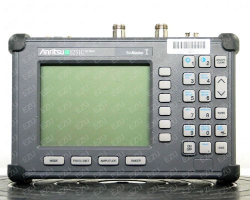
Anritsu S251C Site Master Cable and Antenna Analyzer, 625 MHz - 2.5 GHz
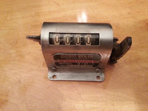
VINTAGE DURANT PRODUCTIMETER MODEL 4-D-1
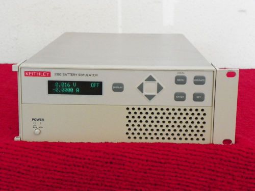
Keithley 2302 Battery Simulator
Metrosonics AQ5000 AQ5001 Air Quality Monitor / Recorder R-Humidity CALIBRATED!!
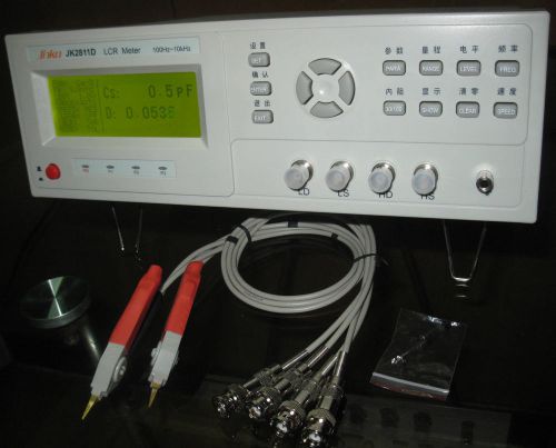
Bench LCR Meter 10KHz Inductance Capacitance RZDQ Test Component Sort JK2811D
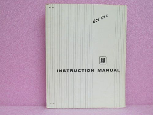
Honeywell Manual 602 C43 Recording Cam-type Program Controller Instruction Man.
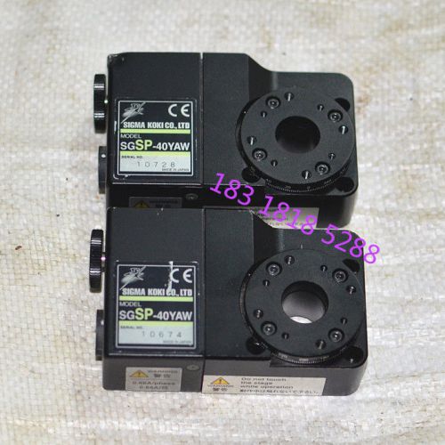
1pcs SIGMA KOKI SGSP-40YAW Rotation Motorized Stage,Stage diameter 40mm #U2U0
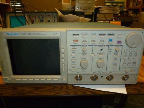
Tektronix TDS 540 Oscilloscope, Sold for Parts L78
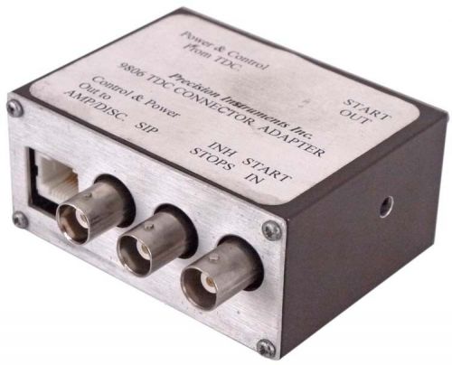
Precision Instruments 9806 TDC Connector Adapter Unit 9-Pin/BNC Ports
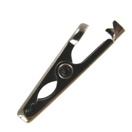
Test Clips CLIP STEEL 5AMP BU-30 (1000 pieces)
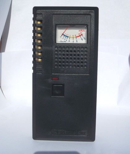
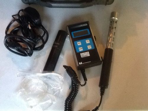
Radiation Detector Meter DX-2 / Colored Analogue Meter NEW made in the USA Boxed
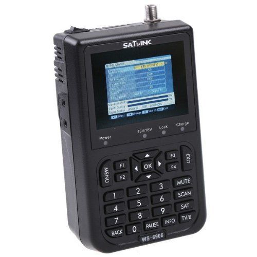
SATlink Satellite Meter Signal Finder Protective Outdoor Screen Display Wireless
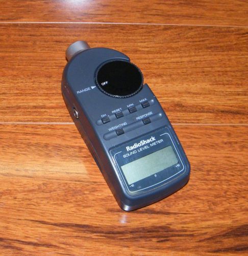
Radio Shack (33-2055) Battery Operated Digital Pressure Sound Level Meter
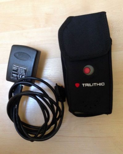
Trilithic Seeker Lite Installation Leakage Detector with charger
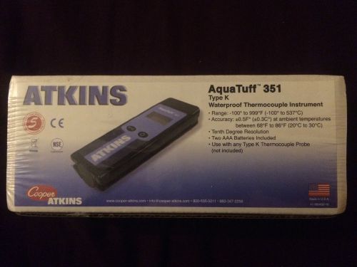
Cooper-Atkins 351 AquaTuff Type K Waterproof Thermocouple
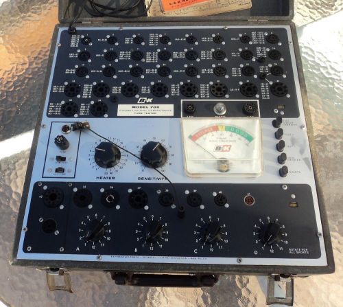
B&K MODEL 700 TUBE TESTER IN NICE WORKING AND COSMETIC CONDITION
By clicking "Accept All Cookies", you agree to the storing of cookies on your device to enhance site navigation, analyze site usage, and assist in our marketing efforts.
Accept All Cookies