US $2.87
| Condition: |
New: A brand-new, unused, unopened, undamaged item in its original packaging (where packaging is
applicable). Packaging should be the same as what is found in a retail store, unless the item is handmade or was packaged by the manufacturer in non-retail packaging, such as an unprinted box or plastic bag. See the seller's listing for full details.
...
|
Brand | Unbranded |
| UPC | Does not apply | ||
| MPN | Does not apply | ||
| EAN | Does not apply |
Directions
Similar products from Light Diods & Lamps
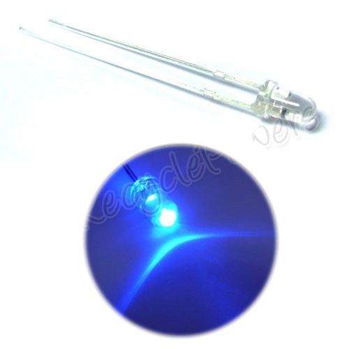
10PCS 1W HP 8mm StrawHat Blue LED 12lm 140° DC 3.2-3.5V
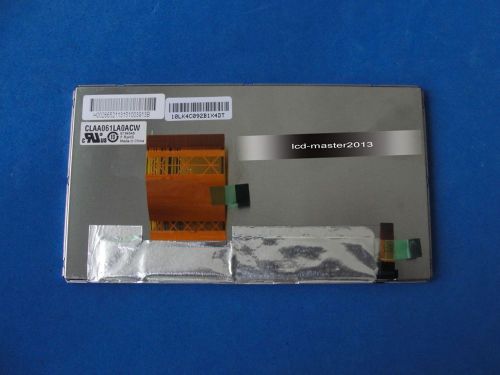
CLAA061LA0ACW Brand New Original 6.1" LCD Display Panel Screen
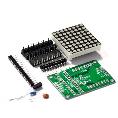
1xMAX7219 Arduino Display Module Cascade Matrix Control Arduino Dot Chip DIY Kit
100 x 3mm Ultra Bright Blue 8000 mcd LED Bulb Light
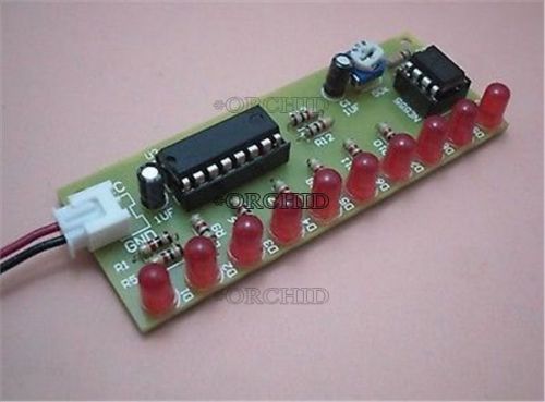
led kit ne555 + cd4017 led lights electronics diy parts electronic kits #3979403
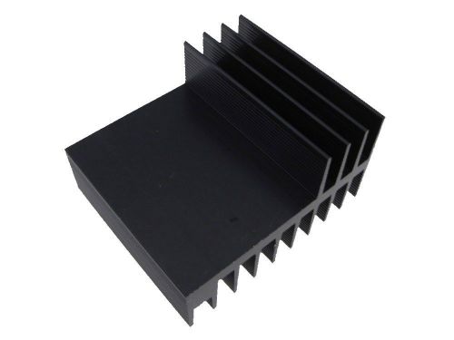
50*58*32mm Aluminum Heat Sink - Black
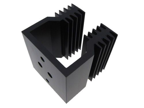
45*44*46mm Aluminum Heat Sink - Black

21"x4" Programmable LED Car Moving Display Sign Board Scrolling Message Red
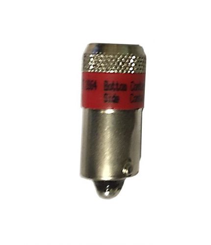
Bulb, Red, 24V, KA2-2021 LED Bayonette
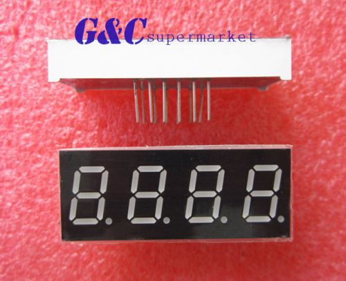
10PCS 0.4 inch 4 digit led display 7 seg segment Common cathode -Red NEW
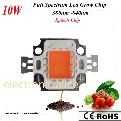
5 pcs New 10W full spectrum led grow chip 380nm~840nm for MJ plant grow/bloom
1 Set of 30W 50W 100W LED 44mm Lens + Reflector Collimator + Fixed Bracket AP
5 lots of Common Cathode 4bit Digital Tube 0.56 Red LED with clock Brand New
50Pcs BA15d Bayonet Parallel Pin Light Bulb Socket,E2
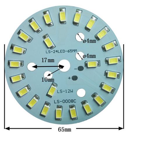
Warm White 5730 12W LED Light Emitting Diode SMD Highlight Lamp Panel 65mm LJN
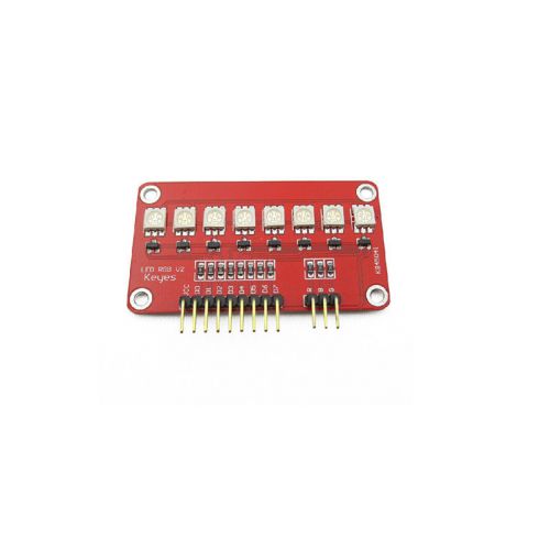
1x RGB LED Module Full Color SCM Light Water Module For Arduino AVR ARM 51 LJN
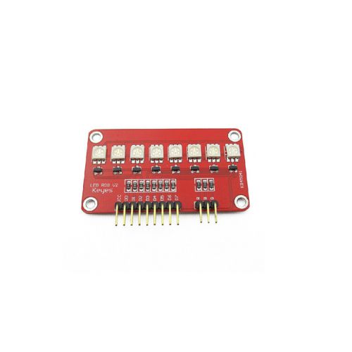
2x RGB LED Module Full Color SCM Running Light Module for Arduino AVR ARM 51 LJN
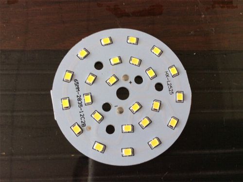
12W SMD 2835 LED Lamp Beads Board Aluminum Plate Ceiling Lamp Conversion LJN
People who viewed this item also vieved
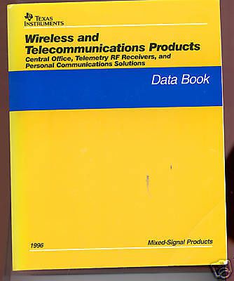
Texas Instruments Wireless & Telecommunication Products
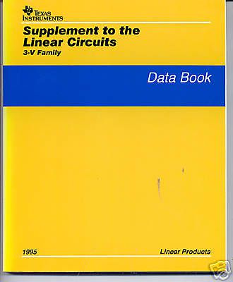
Texas Instruments Supplement Linear Circuits 3-V Family
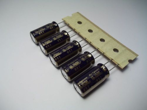
5pcs 1500uF 16v Electrolytic Capacitors 105c Rubycon 10x20 USA SELLER
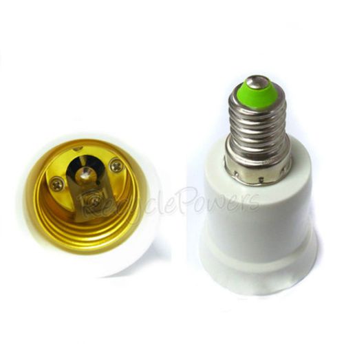
30 pcs Light Lamp Bulb Adapter Converter LED E27 to E14
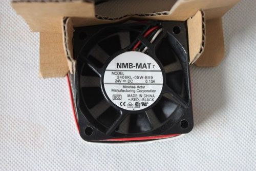
New NMB-MAT 2406KL-05W-B59 24V DC COOLING FAN 60*60*15MM
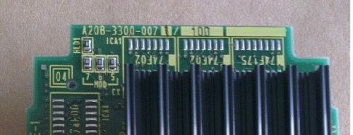
Fanuc A20B-3300-0071 PCB Board Used
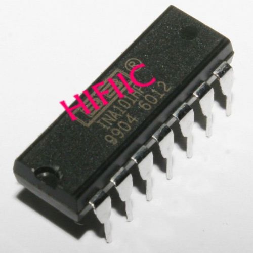
1PCS INA101HP High Accuracy INSTRUMENTATION AMPLIFIER DIP14

OHMITE VITREOUS ENAMELED RESISTOR, #1093, 10 WATT, 150 OHMS, IN BOX
MULTI COLOR MONSTER UNIQUE GIANT ULTRA RARE BIG VFD DIGIT MATRIX DISPLAY TUBE
MONSTER UNIQUE GIANT ULTRA RARE BIG VFD DIGIT MATRIX DISPLAY TUBE USSR. CLOCK
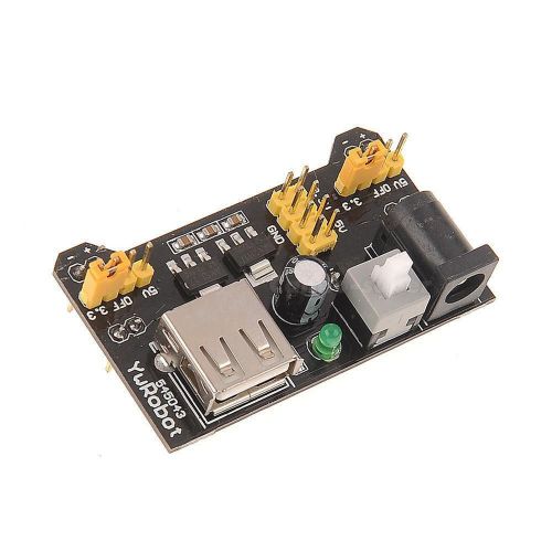
MB102 Breadboard Power Supply Module 3.3V 5V For Arduino Solderless CSAP
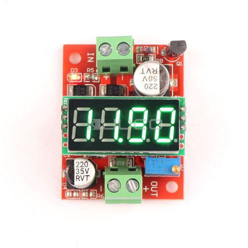
LM2596 DC Adjustable Buck Power Converter 12V 3A + Green LED Voltage Monitor
By clicking "Accept All Cookies", you agree to the storing of cookies on your device to enhance site navigation, analyze site usage, and assist in our marketing efforts.
Accept All Cookies