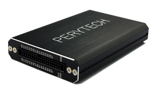
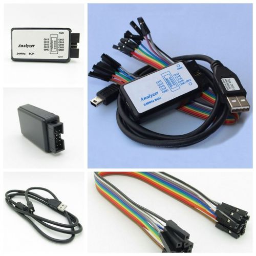
Introduction to Logic Analyzer Peregrine Technology Logic Analyzers provide human-centered operation interfaces and support bus decoding and packet lists. The maximum data compression rate can be up to 1 million times. What is logic analyzer? Peregrine Technology Logic Analyzer Characteristics Peregrine Technology Logic Analyzer Specification What is logic analyzer? The electronic signal is invisible to the naked eye, and it's waveform must be observed and measured by some instruments such as oscilloscopes. Like oscilloscopes, logic analyzers are instruments used for measuring electronic signals. The difference is that oscilloscopes are applied to analog waveforms, and logic analyzers are applied to digital ones (only two status, 0 and 1.) In addition, because of the requirement for measuring digital signals, channels of logic analyzers available are more than those of oscilloscopes (16 or more channels generally). Furthermore, compared with oscilloscopes, the memory size, capacity, and data analysis function of logic analyzers are much larger, so they are more convenient for users to apply them to analyze complex digital data. The comparison table between logic analyzers and oscilloscopes is shown as follows. Oscilloscope Logic Analyzer Measured Signal Analog Digital Number of Channels Less More Memory Size Smaller Larger The analyzed data of a logic analyzer is larger and more complex than those of an oscilloscope, so a larger screen is required to show all of the data. Although logic analyzers are powerful tools, there are fewer users in the early stage because old logic analyzers are too large and expensive. In recent years, the PC-Based logic analyzers are developed. They adopt the screen and computation power of PC to reduce the size and cost significantly, and then logic analyzers are more popular nowadays. What is the different requirement between the logic analyzers and oscilloscopes? Oscilloscopes are applied to measure analog signal, and the most important specification is sampling rate. Higher sampling rate, more detail analog signal variation can be observed. If the sampling rate is not high sufficiently, the captured analog waveform will be critical distortion. Since logic analyzers are applied to measure digital signal with only two logic status, 0 and 1, the distortion issue is less, and the sampling rate can be accepted if it is high enough. There is no more significant assistance for analyzing data by high sampling rate. It will be described by real cases as follows. In the following figure, the upper waveform is captured by an oscilloscope in 2MS/s sampling rate for a given 100 KHz sine wave. There are 20 sample points per period (2M/100K=20), and the waveform can be observed that there is no any critical distortion. The lower waveform is captured by an oscilloscope in 400KS/s sampling rate for the same signal. There are 4 sample points per period (400K/100K=20), and the waveform is distorted obviously to a triangle wave. Therefore, sampling rate is very important for oscilloscopes, and the captured waveforms are critical distortion if the sampling rate is not enough. For the waveform in the upper side of the following figure, the yellow signal is the waveform captured by a logic analyzer in 2MS/s sampling rate for a given signal with 100 KHz clock. There are 20 sample points per period (2M/100K=20). For the waveform in the lower side of the following figure, the yellow signal is the waveform captured by a logic analyzer in 400KS/s sampling rate for the same signal. There are 4 sample points per period (400K/100K=4). When the 2 different sampling rates are compared, there is no any obvious difference between the two waveforms. For logic analyzers, the memory size for measuring is the more important specification. Nowadays, the quantities of digital signal data are all huge, and more memory size can help analyze more data. There is no significant contribution to analyzing signal with by overly obtained sampling rate. On the contrary, consumption of memory is caused as a result. Peregrine Technology Logic Analyzer Characteristics Powerful Data Compression Function Peregrine Technology Logic Analyzers supports the data compression function for more than 1 million times, and it will extend the times for measuring significantly. The fundamental compression principle for logic analyzers: In common cases, logic analyzers will save each sampling signal into memory. After the compression function is enabled, only the content and time length of signal will be saved into memory for all variations. Let's describe it on the basis of a real case. For measuring a given 100Hz clock signal by sampling rate 200MS/s, logic analyzers without compression function can only capture data for 0.65ms. Old logic analyzers own compression rate for maximum 256 times, and they can capture data for 167 ms under the same conditions. The compression rate of each Peregrine Technology Logic Analyzer is maximum 2^20 (two to twenty power), more than 1 million, and it can capture data for more than 640,000ms under the same circumstance. Moreover, 16 channels are available in compression mode. The bar chart for measuring time of 3 kinds of logic analyzers is shown as the following figure. To practice the measure for 640,000ms under the same condition, a logic analyzer without compression function needs 128G memory size. Easy-to-Learn and Friendly User Interface Although logic analyzers are powerful, many researchers still do not utilize them because the time for learning is too long for most logic analyzers. More than 1000 pages are contained in the user manuals of many logic analyzers. Since there is no enough time to learn one tool for most research generally, researchers have no chances to apply the powerful tool often. Understanding users’ requirements, Peregrine Technology aims to develop the logic analyzers with the most easy-to-learn and friendly user interface. All operations of Peregrine Technology Logic Analyzers are so intuitive that users can utilize all functions successfully almost without user manual. Reduced operations can support each functions by the fewest steps. Moreover, many friendly functions are developed to observe signals and analyze data. Brief Tool Bar Only most-frequently-used functions are reserved in the tool bar to avoid confusing users. Icons for functions are all simple and meaningful enough to be remembered for many years. Advanced functions are shown in the pull down menus. Only Two Steps for Measuring Signal STEP 1: Select the trigger conditions. 6 basic trigger conditions can be selected: Rising Edge, Failing Edge, Either Edge, High, Low, and None. You can switch trigger conditions by the left key of mouse, or select one trigger condition by the option menu displayed by the right key of mouse. STEP 2: Press RUN button. When the trigger condition is met, the Logic Analyzer will transfer data to PC for display and analysis. Friendly Operation Interface Peregrine Technology Logic Analyzers provide very friendly and full function interface for observing the waveform and signal. You can move to the region you want to observe by right-clicking on and drag the screen anytime. Moreover, you can move the screen by mouse wheel, and practice the zoom-in/out function by Ctrl + mouse wheel. In addition, more convenient hot keys are provided. The hot keys for observing screen of Logic Analyzers are listed as follows. Hot Key Function Right Key of Mouse Drag the Screen Wheel of Mouse Move the Screen Left/Right Key on the Keyboard Left/Right Move the Screen Page Up / Page Down Key on the Keyboard Go to Previous/Next Page Ctrl + Mouse Wheel Zoom In/Out the Screen +/- Key on the Keyboard Zoom In/Out the Screen Ctrl + Left/Right Key on the Keyboard Go to the Edge of Previous/Next Waveform Page Up / Page Down on the Keyboard Go to Previous/Next Page Left Key of Mouse Move Cursor (A, B Bar) Alt + A / B / T Key on the Keyboard Go to the Position of A / B / T Bar Convenient Channel Panel Function The Channel Panel in the left of screen can be used to configure the channels for measuring. You can set up the name of channels and buses, add/remove channel, copy/paste channels, and change the color of channels. You can also select your required channels by Ctrl + the left key of mouse, and then group the channels into one bus. Bus Analysis Function Are you still decoding I2C bus manually? Time of blurred vision is over. Peregrine Technology Logic Analyzers support the bus decoding, and it can analyze each kind of bus values for saving your development time and effort significantly. It is the real circumstance for analyzing I2C bus by a Peregrine Technology Logic Analyzer as the following figure. Peregrine Technology Logic Analyzers also support the Package List Function. The function shows the decoded packets sequentially in one individual window. It is easier to administrate the packet transmission since you can check more data in one window. The following figure is screenshot of the window for showing packet list of I2C bus. Peregrine Technology will increase new bus analysis function continuously, and you can tell us your requirement for new bus analysis function anytime. Cursor Function The option menu of Cursor Function will be shown after right-clicking on the Rule Area, in the top of screen. You can put A and B cursors, or go to the positions of A, B, T (Trig) cursor. You can drag a cursor by the left key of mouse. When you drag a cursor near the edge of waveform, it will align to the edge automatically after the left key is released. Data Filter Function Sometimes, only a small portion of huge data is needed, and the Filter function can be applied for filtering the required data. It is a SPI signal in the following figure. Since the duration between data is longer, only one data is shown in the screenshot. Observing the SPI signal, we can find that all "Enable Signal (Brown)" are Low status during data transmission. At the moment, we can configure the Filter function for capturing data when the "Enable Signal (A0)" is Low as the following figure: After configuring filter, the signal waveform can be captured as the following figure. When "Enable Signal" is "High," data will be filtered except the data of "Low" of the "Enable Signal." The function, "Separate Data," can keep one filtered data for separating data in order for data analysis. The default value of "Separate Data" is checked, and it can be disabled by yourself. Frequency Counter Function Frequency Counter can support the measure for signal frequency. For the frequency counter of each Peregrine Technology Logic Analyzer, the maximum significant digit is up to 10, maximum degree of accuracy can research 0.1 Hz, and highest measuring frequency is up to 200 MHz. You can choose the Reflash Period from 0.2 second to 10 seconds. Moreover, 2 Clock Input Channels can be selected for the input of frequency counter. CLK channel is the one with 500 ? input impedance and 200 MHz frequency bandwidth, and the level cannot be adjusted. B7 channel is the one with 500 ? input impedance, 100 MHz frequency bandwidth, and the adjustable level. Bus Export Waveform Function Software supports the function that the waveform can be exported to a text file for your advanced analysis or for being fetched by other programs as the following figure. The related information at the head of the text file can be selected for appearance or not in the option menu. In addition, Peregrine Technology Logic Analyzers support other hardware functions, and they are introduced briefly in the following limited space. Trig Width: It can be adjusted to be triggered when the signal is greater than or smaller than certain specific width. Trig Delay: It supports to generate the trigger signal for a specific duration after the trigger condition is met. It can be used for observing the signal of the specific duration. Noise Filter: In the environment with many noises, hardware glitch filter can support to filter noises by selecting 1 or 2 sampling time width. Always free for upgrading software, firmware, and bus: Except partial models with specific description, almost Peregrine Technology Logic Analyzers offer free service to upgrade the software and firmware all the time (including bus.) Logic Analyzer Physical Appearance Peregrine Technology Logic Analyzers adopt black aluminum alloy case plus hair-line surface treatment so that their appearance is fashionable with good texture. They are easy to carry around because of their lighter and smaller hardware. The words on the panel and case are written by laser engraving technology. They are attractive. Also, they do not have the flaking issue for paints or labels. The demo mode is supported by our software, so you can try the software without hardware first. Here is thesoftware download webpage. Welcome to download the software for trial. Peregrine Technology Logic Analyzer Specification Specification / Model PLA-1664 PLA-16128 PLA-32128 PLA-321M PLA-322M Channels 16 16 32 32 32 RAM Size per Channel 64k 128k 128k 1M 2M Max Sample Rate 200MS/s Max External Clock Input Frequency 200MHz Bandwidth 100MHz Max Compression Ratio 2^20 (More than 1 million) Available Channels for Compression 16 Data Filter Support filtering independently or with compression functions Noise Filter Support hardware glitch filter with 1 or 2 sampling width Trig Condition Rising Edge, Failing Edge, Either Edge, High, Low, None Trig Width Support trigger condition that signal is greater than or less than specific Width Time Trig Position Adjustment Trigger position can be adjusted for occupying 10% to 90% of memory, and the default value is 50% Trig Delay Function Support Trig Voltage Range +6V ~ -6V Trig Voltage Resolution 0.1V Max Input Voltage ±30V Bus Decode II2C, SPI, UART, I2S, PS2, 1-Wire, USB 1.1, S/PDIF, SD (be on the increase) Bus Upgrade Always free Bus Packet List Support Bus Export Waveform Support Input Impedance 500K? / 10pF OS Support Windows XP / Vista (32 & 64) / Windows 7 (32 & 64) / Windows 8 (32) Interface USB 2.0 Dissipation Power < 2.5W Power USB (DC 5V, 500mA) Size 134 x 89 x 24 (mm)
By clicking "Accept All Cookies", you agree to the storing of cookies on your device to enhance site navigation, analyze site usage, and assist in our marketing efforts.