US $145.00
| Condition: |
New: A brand-new, unused, unopened, undamaged item in its original packaging (where packaging is
applicable). Packaging should be the same as what is found in a retail store, unless the item is handmade or was packaged by the manufacturer in non-retail packaging, such as an unprinted box or plastic bag. See the seller's listing for full details.
...
|
Brand | ELECTRONICS |
| Country/Region of Manufacture | Greece | ||
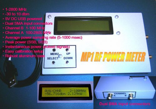
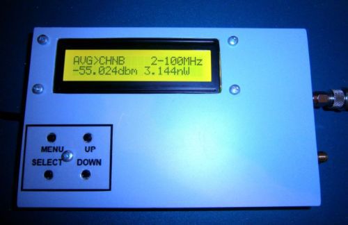
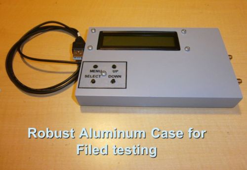
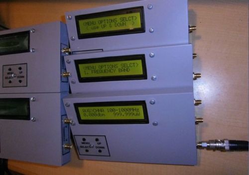
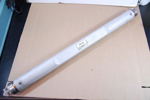
| Model | MP1 RF POWER METER 1 MHz to 2.8 GHz |
Directions
Similar products from Plug Energy Meters and Power Meters
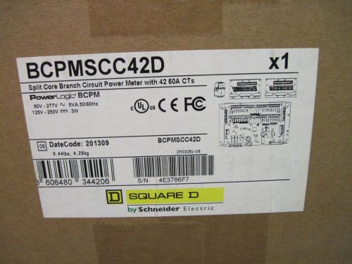
Square D Schneider Electric BCPMSCC42D Branch Circuit Power Meter w/ CTs**New**
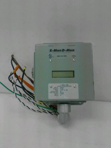
E-Mon D-Mon Model #480400CE Kit Low Profiling kwh/kw meter includes CT's
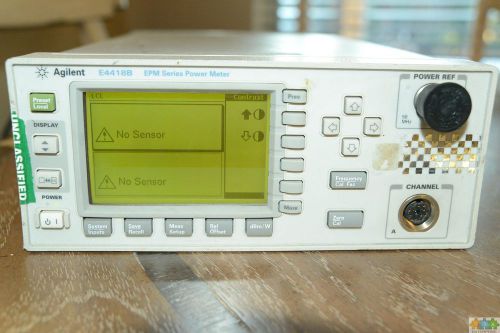
Agilent/HP E4418B EPM Series Single-Channel Power Meter AS IS
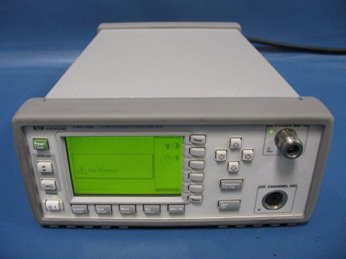
HP E4418B EPM Series Power Meter | RF Power Meter | No Probe
EU Energy Meter Watt Voltage Volt Tester LCD Power Monitor Analyzer Smart Socket
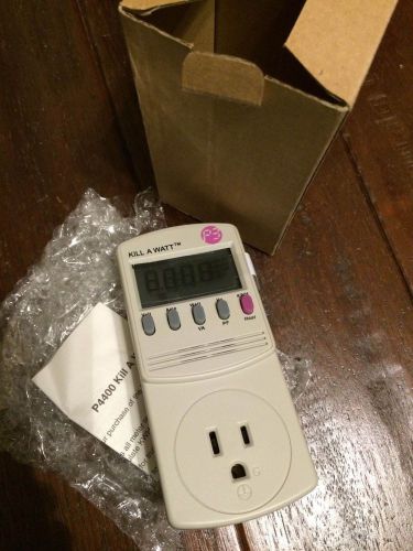
P3 KILL-A-WATT P4400 Energy Meter. Empowers you to save $100's on your electric
LED Energy saving lamp Tester Power Meter Power Factor Electricity detectors
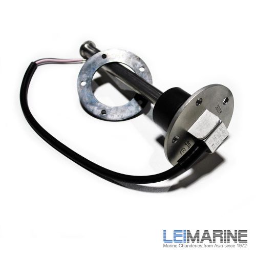
KUS S5 Fuel Level Indicator Tank 150mm 12V/24V for Car Marine Boat New
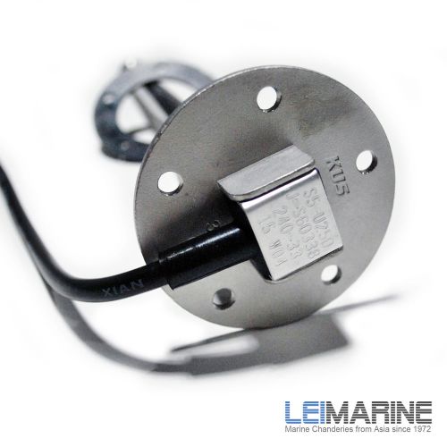
KUS S5 Fuel Level Indicator Tank 250mm 12V/24V for Car Marine Boat New
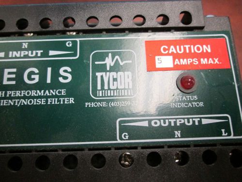
Tycor, Transient/ Noise Filter, AGS-120-5-X, 120V, 5A, Used
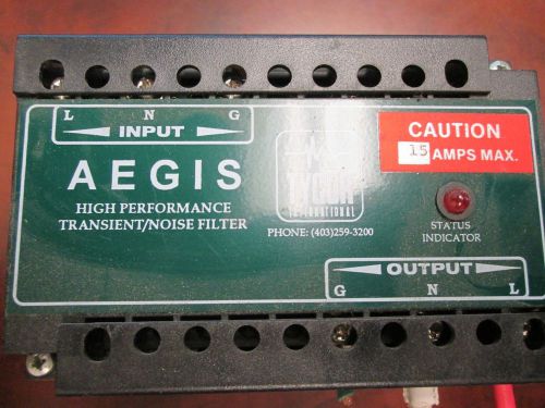
Tycor, Transient/ Noise Filter, AGS-120-15-X, 120V, 15A, Used
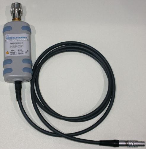
Rohde & Schwarz NRP-Z91 AVG Power Sensor 9 kHz - 6 GHz
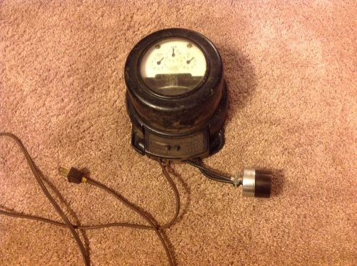
1909-13 General Electric GE I-10 Thomson Watthour 3 Dial Power Meter, 2 Wire
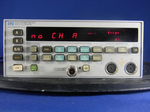
Agilent 438A Dual Channel RF Power Meter with sensor cables 30 Day Warranty
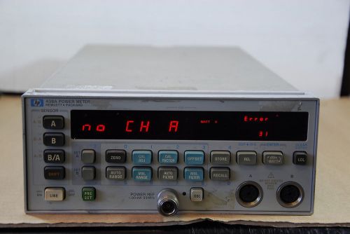
HP 438A POWER METER with Option 002
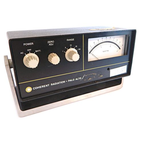
Coherent Radiation Laboratories Palo Alto Power Meter Bench Model 2011
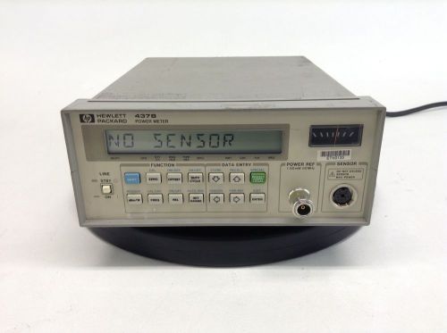
Hewlett Packard 437B Power Meter
People who viewed this item also vieved
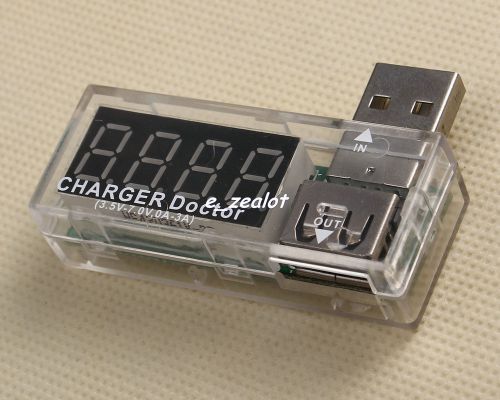
Translucent USB Current/voltage Tester Detector ammeter 0A-3A 3.5V-7V Perfect
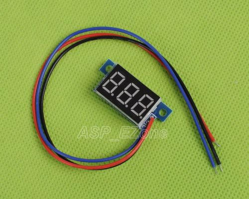
1pcs Blue LED Panel Meter Digital Voltmeter DC 0-99.9V New
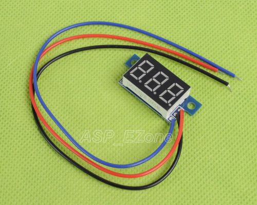
1pcs RED LED Panel Meter Digital Voltmeter DC 0-99.9V
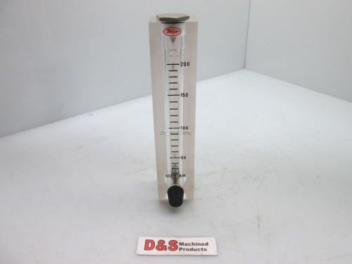
Dwyer VFB-55-BV Flow Meter 0-200 SCFH AIR 1/8" NPT
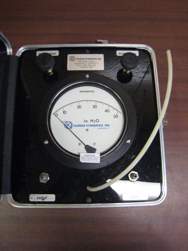
Flow Meter Differential 0-50 in. H2O Flordia Hydronics Inc. FREE SHIPPING
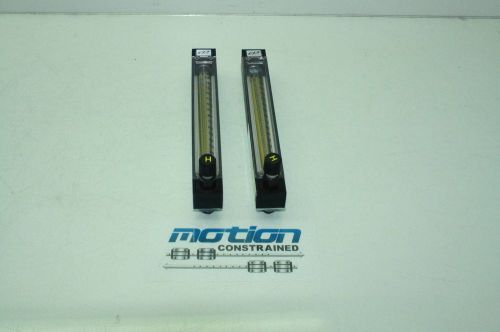
Lot of 2 Cole-Parmer P04/1-N044-4 150-mm Correlated Flowmeters 1/8" NPT
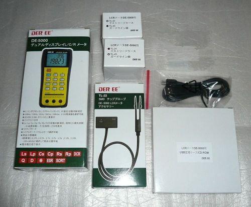
DER EE DE-5000 High Accuracy Handheld LCR Meter with TL-21 TL-22 TL-23 PCLink
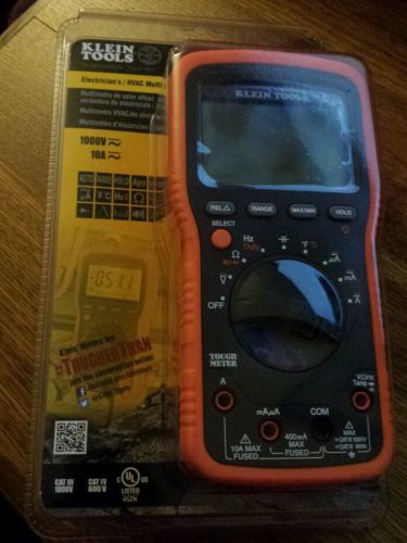
Klein Tools MM1000 Electrician's / HVAC Multimeter - NEW **Free Shipping**
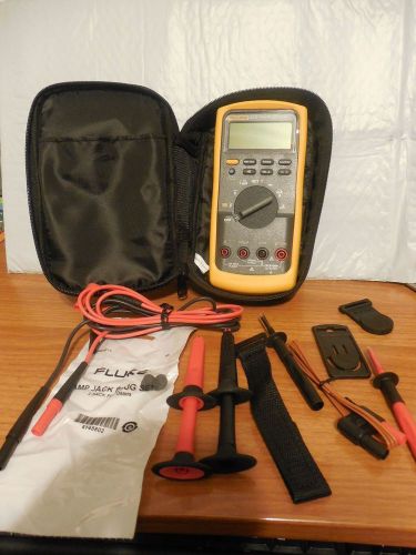
Fluke 87V/E2 Industrial Electrician Combo Kit
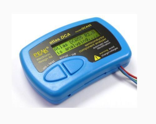
Peak DCA55 Atlas Semiconductor Analyser Full automatic discrimination
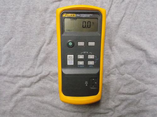
Fluke 714 Thermocouple Calibrato
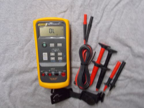
Fluke 712 RTD Process Calibrator
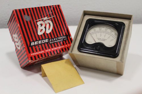
BEEDE ELECTRICAL INSULATION RESITANCE LEAKAGE CURRENT MILLIAMPERES 0-2500M 0-500
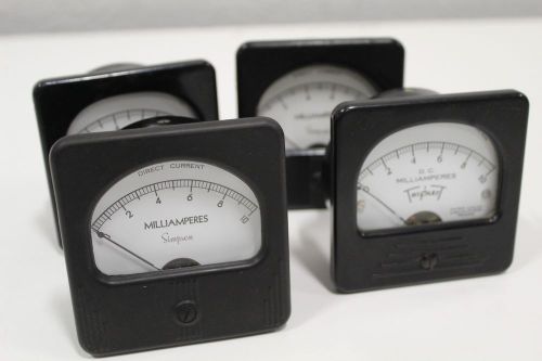
Lot of (4) Simpson Triplet Milliamperes Meter 0-10 D.C. 327-T +Free Expedited SH
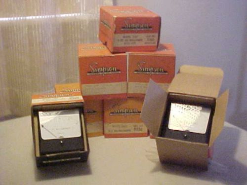
SIMPSON METERS LOT OF 8.PC'S NEW.DC MILLIAMP METERS 0 TO 20 AND 0 TO 5
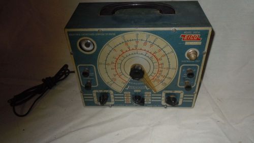
Vintage EICO R/C Capacitor Resistor Bridge Tester Model 950A Scientific Electric
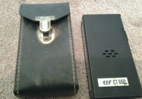
Tif660 Capacitor Tester with case
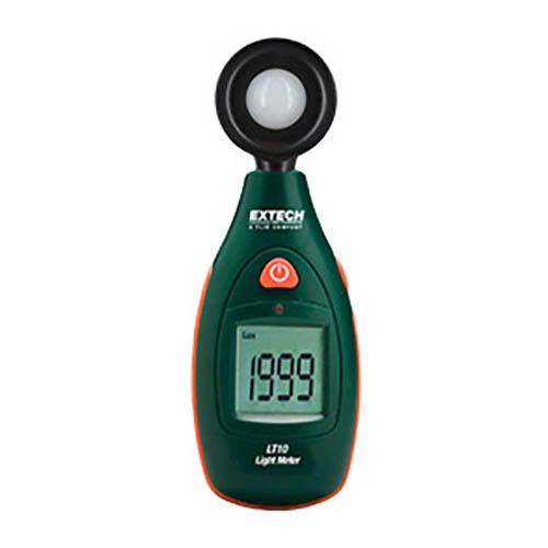
Extech LT:10 Pocket Series Light Meter Compact, One-Button Operation Light Meter
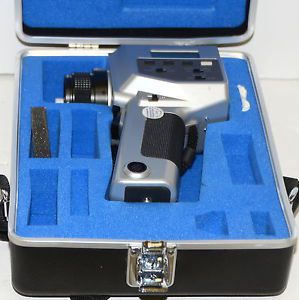
Konica Minolta CS-100 Chroma Colorimeter CS 100
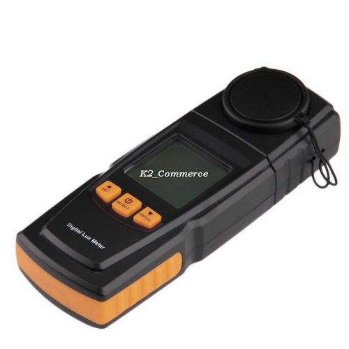
GM1020 LCD Display Handheld Digital Light Meter Photometer Up to 200,000 Lux K2
By clicking "Accept All Cookies", you agree to the storing of cookies on your device to enhance site navigation, analyze site usage, and assist in our marketing efforts.
Accept All Cookies