US $3,408.25
| Condition: |
New: A brand-new, unused, unopened, undamaged item in its original packaging (where packaging is
applicable). Packaging should be the same as what is found in a retail store, unless the item is handmade or was packaged by the manufacturer in non-retail packaging, such as an unprinted box or plastic bag. See the seller's listing for full details.
...
|
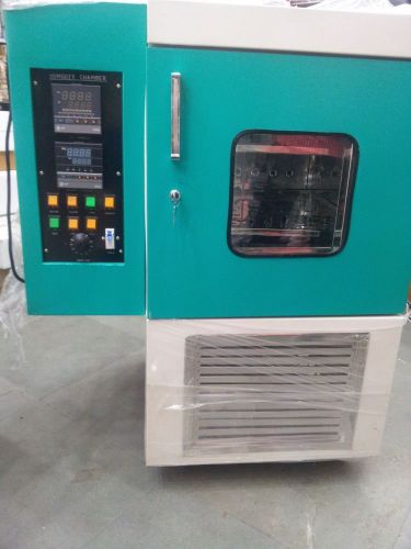
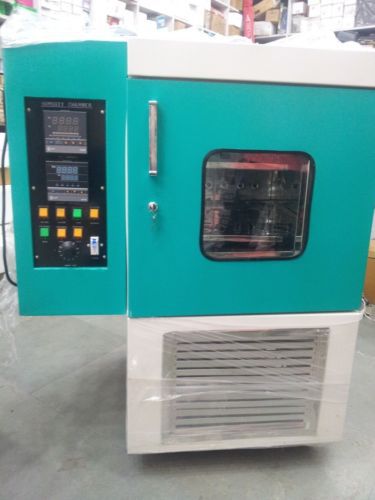
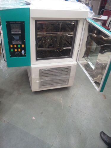
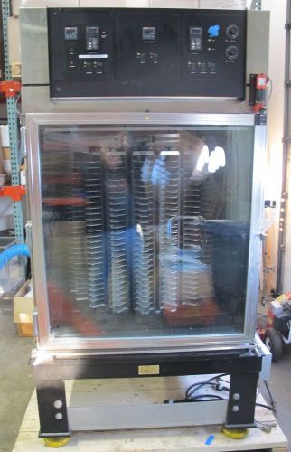
Brand | labapp |
| MPN | Does Not Apply | ||
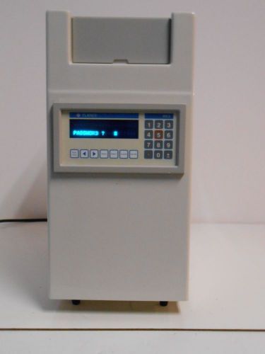
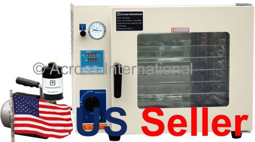
| Model | lab-254 | ||
| Country/Region of Manufacture | India |
Directions
Similar products from Environmental & Testing Chambers
SUN Systems EC01 Test Environment Temp Chamber Rev. E: -100?C to +300?C, 0.7 FT?
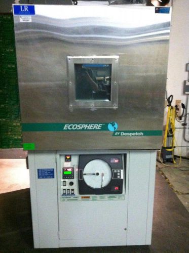
Despatch Esosphere EC619 Temperature Humidity Chamber
Thermotron SM-5.5 Temperature/Humidity Cycle Chamber
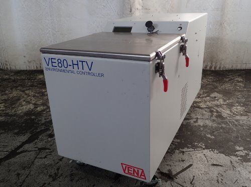
VENA VE80-HTV CHILLER / ENVIRONMENTAL CONTROLLER 10" X 10" X 12" CHAMBER
Power Scientific Stability Chamber
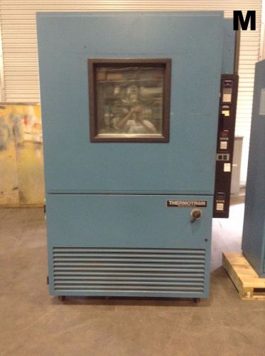
Thermotron SM-32C Test Chamber Enviromental Humidity / Temperature Chamber
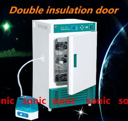
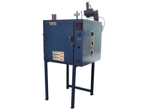
LAB Humidity Chamber Temp. & Humidity Incubator Lab Medicine Assay Box S
Espec SH-240-S1 Bench-Top Temperature & Humidity Chamber 0.8 cu. -40°C to +130°C
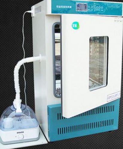
LAB Humidity Chamber Temp. & Humidity Incubator Lab Medicine Assay Box
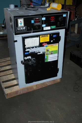
Cincinnati Sub-Zero CSZ-5 Environmental Temperature Test Chamber Oven
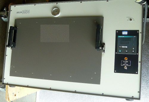
Delta Design Environmental Test Chambers (Oven) 9064
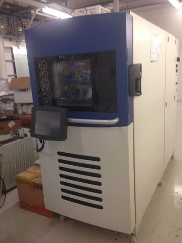
Weiss, TS-120, Temperature Shock Test Chamber
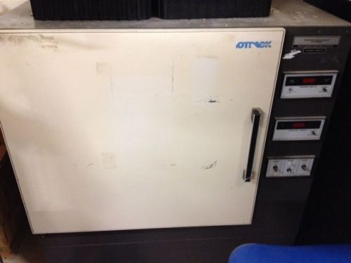
Hotpack 435314 temperature humidity environmental chamber in Broomfield, CO
Mint!!! Thermotron S-4-3800 (S4C) Temperature Chamber/ -70C to +180C / 4 mo Wrty
Coy Laboratories Hypoxic anerobic glove box 3' x 3' x 3' feet
Selling Used, Tested VWR Scientific Temperature Chamber 9050
Vena VE80-HTV Environmental Controller with VC10 Chamber
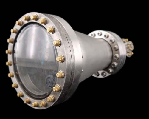
MDC Industrial Lab ION Pump Vacuum Research Chamber Assembly System Unit
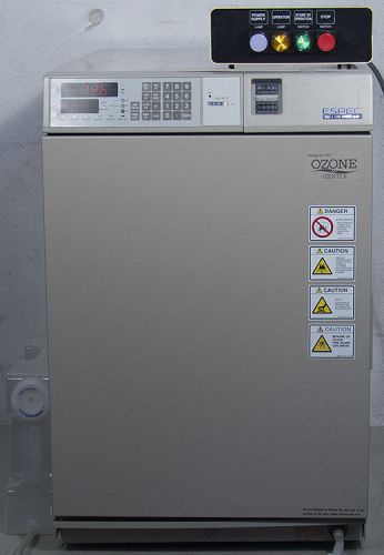
Thermo Electron 3851 Incubator / Microplate Environmental Chamber
SUN ELECTRONIC EC16 EC-16 LAB TEMP TEST ENVIRONMENTAL CHAMBER OVEN 177C EC16HA
People who viewed this item also vieved
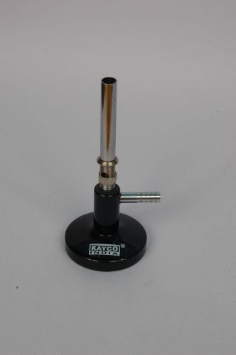
Bunsen Burner, Heating and Cooling Lab Equipment, Educational Aid, Burner,
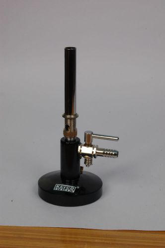
Bunsen Burner with Stop Cock,Heating and Cooling Lab Equipment, Bunsen Burner,
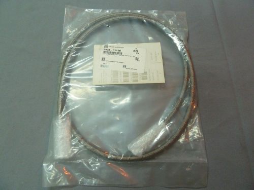
AMAT AMAT3400-01299 Braid Hose Assy Flex Cord 3/8 ID x 72”
SET OF 4 EKLIND SECURITY PENT-L 1/4"
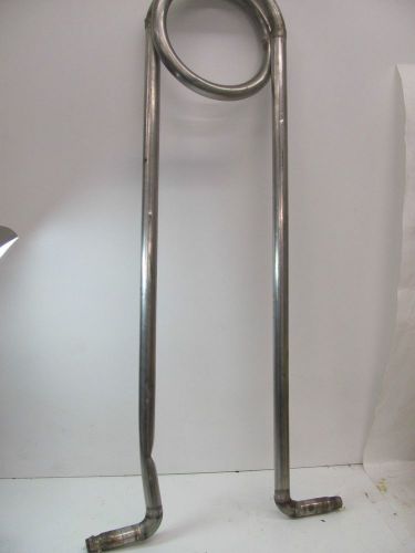
STAINLESS STEEL COOLING/HEAT EXCHANGER 35" L X 9 1/4" W OD 1" ID 9/16"
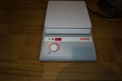
daigger digital hot plate EF5035B 120 volts 7"x7"
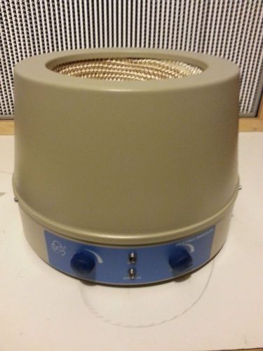
Electric Heating Mantle and magnetic stirrer, 2000 ML
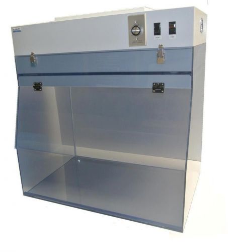
Portable Laminar Flow Hood- 24" Width- Static Dissipative PVC
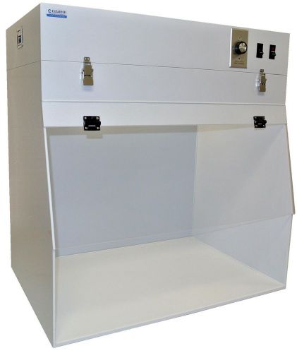
Portable Laminar Flow Hood- 32" Width- Polypropylene
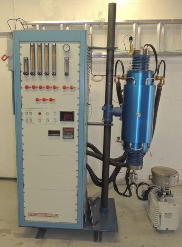
Thermal Technology High-Temperature Vacuum Tube Furnace
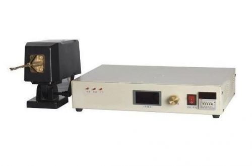
5KVA 700~1500KHz 5KW Ultrahigh Frequency Induction Heater Furnace-New
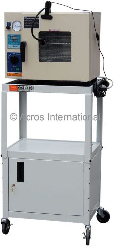
Adjustable Steel Mobile Cart w/ Key-Lock Cabinet for 0.9 Cu Ft Vacuum Ovens
AI 1.9 Cu Ft 16x14x14" Vacuum Degassing Chamber Drying Oven w/ 7.2 CFM Pump
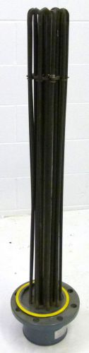
Warren Electric Corp. XWF-24-460-42*3 Flanged Immersion Heater 460VAC 24KW *NEW*
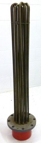
Chromalox TM0-1230 Flanged Immersion Hot Oil Heater 40" 480V 1-3PH 30KW *NEW*
Tutco CH280-6 Compressor Crankcase Heater 70W 575V ! WOW !
2 - Pyco 12" temperature probe K-250-304-D-12-B-2A NEW
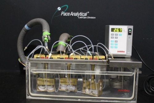
Julabo MD-Basis Heating Immersion Circulator
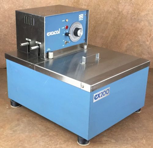
Neslab Circulating Water Bath * Model: exacal ex200 * Heat Only * Tested
By clicking "Accept All Cookies", you agree to the storing of cookies on your device to enhance site navigation, analyze site usage, and assist in our marketing efforts.
Accept All Cookies