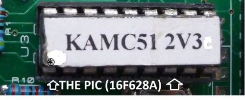
Controller short Kit for the AD9851 DDS Signal Generator Module. NOTE: There will be no output from the AD9851 DDS Signal Generator Module sold on E-bay without a Controller like this or an interface circuit and a computer and software. This controller circuit and code will provide the functions (see the Specifications) to control a LCD Display and the AD9851 DDS Signal Generator Module and can also suffice as an interface if you wish to write your own code to control the modules. PIC 16f Controller for the AD9851 DDS Signal Generator Module. AD9851 DDS Signal Generator Module Controller Kit. by KAMCODE Microchip PIC Pre Programmed with software To experiment with the AD9851 DDS Signal Generator Module 0 to 70MHz The software also Drives a 2 line by 16 character LCD display to display the AD9851 DDS modules set frequency. This is a nice little project for some one or a club who are interested in Electronics, Radio or Audio to build up it provides a stable little signal source to play with and it can replace VFOs, Crystals ect. as a stable frequency source. It provides 2 clean sine wave output @approx 1.0 V p-p (no load 50ohm o/p Z) and 2 square wave outputs TTL. The sine and square outputs are 180 deg. output of phase with each other. Refer to the AD9851 modules spec. Build it up the way you like, use any method (the construction layout is not critical and easy to follow), add output Buffers to the outputs if required and maybe filters for HF stuff and you have got a very stable Signal generator.You will find loads of use for it. If you are into Electronics like me and fancy building some hardware from scratch and don't want to mess with software try this. and if you build it and it don't work there is plenty of help and support. I loathe software do you?..but we need it here. to see the components required google "image AD9850 DDS SIGNAL MODULE - COMPLETE PIC CONTROLLER KIT". So Grab a Pre-programmed PIC Chip and find the other parts need (probably you have got them in your junk box) and get out your soldering iron and have a go, and when you have built it and if it don't work there is plenty of help and support available so no worries. The hardware is simple to construct on either a PIC16f628 universal prototyping board or on a small bit of matrix board.Or you can make up your own PCB. The circuit uses up to 9 Switches for input or only 2 switches if you intend to use the comms port, or it will work with 1 switch and the encoder as a simple VFO. The PIC code can be controlled by the comms port only (ie no switches or LCD display), please make a request if you require this version. The Kit consist of 1 off Pre-programmed Pic Chip plus Instruction Manual and Circuit diagram. NOTE The AD9851 DDS Signal Generator Module 0 to 70MHz IS NOT INCLUDED it can be obtained off E-bay search for AD9851 DDS Signal Generator. The 2 line by 16 character LCD display or the Rotary Encoder IS NOT INCLUDED they can be obtained off E-bay. If you can't be bother to rummaging through your junk box, then a complete kit of all passive components Including is also available at a small cost. FOR YOUR NEW or OLD RIG....... YOU NEED SOMETHING LIKE THIS TO CALIBRATE AND TEST YOUR RIG PROPERLY. YOU CAN TEST FOR FREQUENCY ACCURACY, SENSITIVITY, INTER-MODULATION PRODUCTS , IMAGE REJECTION, DYNAMIC PERFORMANCE, ECT. USING TWO MODULES. WITH ONLY ONE MODULE YOU CAN TEST AND TUNE UP FILTERS, AND IF YOU ARE AN HI-FI OR ROCK BAND PERSON YOU CAN CHECK OUT YOUR AMP AND SPEAKERS FOR CLEAN RESPONSE OVER THE FREQUENCY RANGE. IF YOU ARE A SHORT WAVE LISTENER YOU CAN USE IT TO CHECK YOUR RECEIVER SCALE CALIBRATION AND FIND THE EXACT FREQUENCY YOU ARE TUNED TO. AND IF YOU HAVE AN OSCILLOSCOPE YOU CAN CHECK AND CALIBRATE THE TIME BASE AND CHECK THE "Y" AMP. OTHER USES: VIBRATION TESTERS, SINEWAVE INVERTERS, WAVE GENERATORS,MOTOR DRIVES ECT. HEARING FREQUENCY RANGE TESTS. PIC Code Specifications: O Controls the AD9851 DDSG Module (DDSGM) to set up its frequency and Phase values. O Drives a 2 line LCD display to display the AD9851 DDSGM Frequency & Phase. O Display format: first line “00,000,000.0 Hz” second line Phase “00.00 deg” M1. O Maximum set frequency “89,999,999.9” Minimum set Frequency “00.000.000.0” Hz. O Maximum display frequency in display Xn mode “999,999,999” Minimum set Frequency “000,000,000” Hz. O Drives 1 or 2 AD9851 DDSGM M1 or M2 (use for testing Rf amps/mixers ect.). O Frequency set steps; 10MHz,1Mhz,100KHz,10KHz,1KHz,100Hz,10Hz 1Hz 0.1Hz . Or in Channel mode: 0.5KHz,1Kz,2.5Kz,5Kz,10Kz,12.5Kz, 25Kz,50Kz or we can program in your own channel steps. O Supports Shaft encoder using cheap rotary encoder. O Frequency can be continuously incremented / decremented in the above steps or channel. O VFO mode RX, adds or subtract user, programmed offset frequency from the LCD displayed frequency. O VFO mode TX, negates programmed offset frequency from the LCD displayed frequency. O The LCD displayed frequency now can be set to display XN times the modules frequency the range of Xn is selected by the user from 1X,2X up to 32 times, this feature enables the use of frequency mixers, phase lock loops/VCO or frequency multipliers to extend the frequency range in applications. O 40 bit frequency calculation for excellent accuracy down to 0.1Hz. O Frequency Calibration function enables output frequency to be calibrated to better than one part per million (1ppm). O Swap the frequency value of M1 to M2 or M2 to M1 (usful for testing band edges of filters) O Copy the frequency of M1 to M2 or M2 to M1, (used for RT) O Sweep frequency Generator function in any step value to the max. frequency. the sweep function now has Dwell time added it enables easy measuring at each frequency step. the Dell time range is approx. 50 ms. to 7 Sec. settable in 0.25 Sec. steps. (useful for scan function or vibration tests) O Wobbultaor function any set frequency value to the max. frequency. O Phase modulation of the set frequency (useful for testing and tuning onto the test signal). O Saves the M1 and M2 frequency and Phase and options in the PIC electrically erasable random memory (EERAM). O Can be controlled by users own micro-controller to write to the LCDD or the AD9851 DDSGM. O Support TTL RS232 Serial communication to control the AD9851 DDSGM. (for connection to a computer a TTL to RS232 Com port interface or a TTL to USB port interface will be required). O Comms user interface, There are more than 27 commands implemented in the code to control the DDSGM via a dumb terminal or serial Apps running on a computer,Tablet computer or mobile phone. no special software needed. +++++ CONTROLLER PIC FOR THE AD9850DDS Module is also available send a request if you want this version +++++
By clicking "Accept All Cookies", you agree to the storing of cookies on your device to enhance site navigation, analyze site usage, and assist in our marketing efforts.