US $150.00
| Condition | For parts or not working
:
An item that does not function as intended and is not fully operational. This includes items that are defective in ways that render them difficult to use, items that require service or repair, or items missing essential components. See the seller’s listing for full details.
|
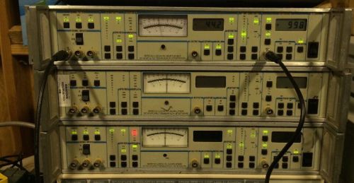
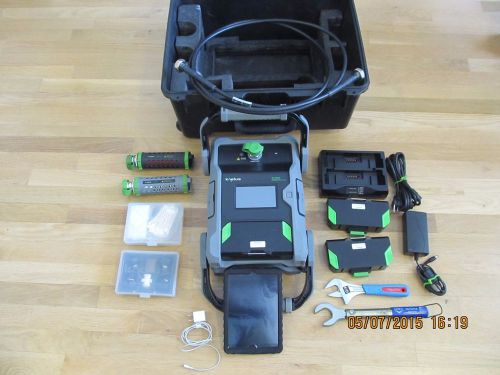
| Seller Notes | “Old unit, scratches and some permanent marks around. Inputs and outputs work fine, all tested. GPIB working with general issues of SR510 (meaning you will need to add a long GPIB cable or some other "monkey" business to make GPIB work on labview or other system).” |
Directions
Similar products from Other Equipment for Electrical Testing
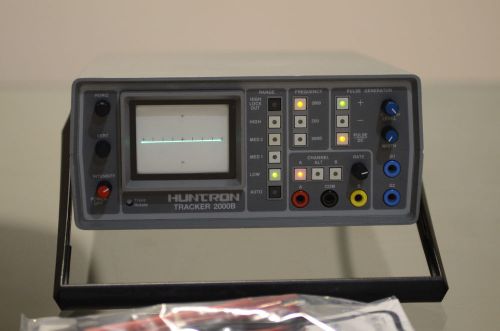
Huntron Tracker 2000 Electronic Semiconductor Component Tester Circuit Analyzer
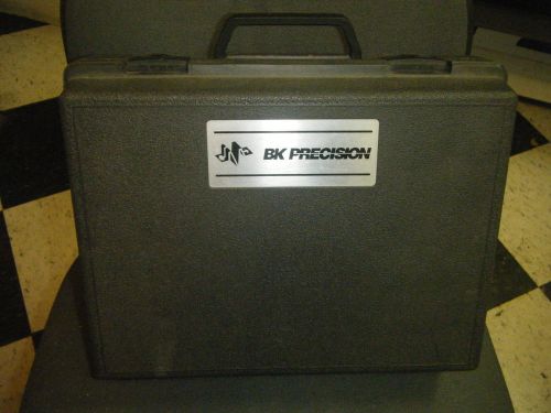
BK Precision Model 490 Analyzer Rejuvenator W/Case, and 1 Adaptor
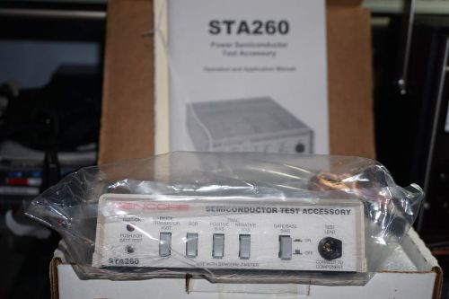
SENCORE STA260 SEMICONDUCTOR TEST ACCCESSORY
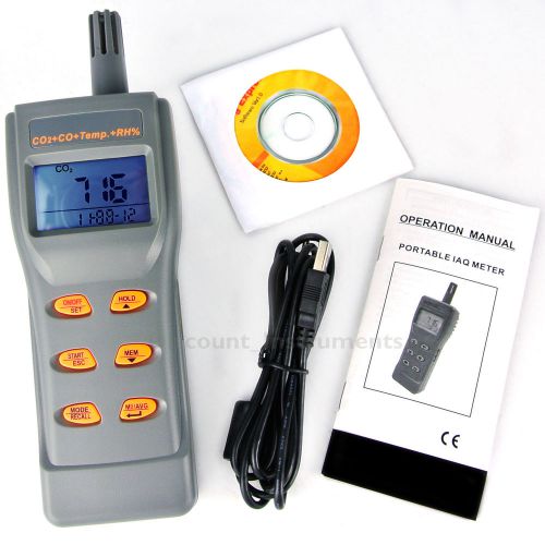
Portable Digital IAQ Monitor Hygrometer CO2 CO Temp. RH DPT WBT Meter Generic
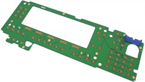
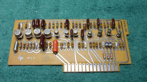
HP Agilent 08360-60001 Circuit Board Assembly Plug-In Card Module A-2918-45
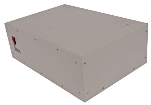
Prometrix 500W 115V Dual AC Output Power Source Unit w/SSI SQV140-1322
SyntheSys BERTScope 12500A 12.5Gb/s Digital Bit Error Rate Analyzer BERT Tester
HP Agilent 81200 1Kb/s-2.7Gb/s Data Generator/Analyzer Modular Platform HP-IB
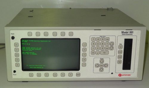
Quantum Data 901 Video Signal Generator
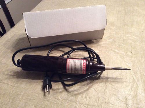
Electro Technic BD-10AS Spark Tester – No Reserve & Free Shipping
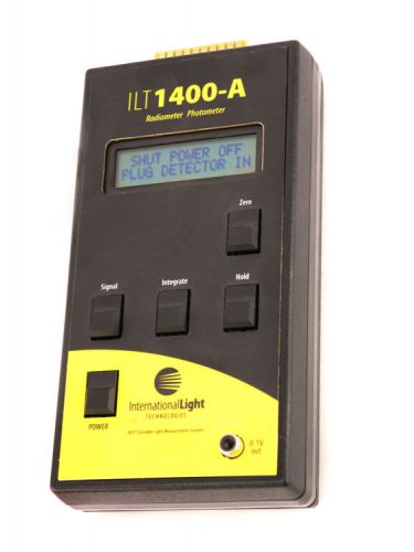
ILT 1400-A Radiometer Photometer International Light Technologies ILT1400A
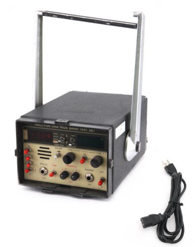
Halcyon 704A Wide Band Test Set TIMS Transmission Impairment Measuring System #4
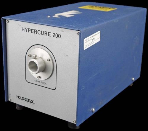
Hologenix Hypercure 200 UV Curing Unit Light Guide Module Industrial #1
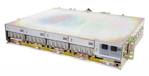
Astec AP6C6603 Power Switch Breaker Modular Chassis AP6C64BA AP6C64CA PARTS
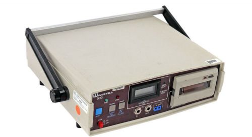
Westell 30G Portable Benchtop Digital Display Time Test Tracker/Recorder Printer
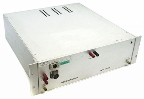
Pacific Instruments 0A8885-1 Multi Input Test Fixture
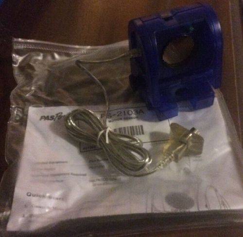
PS-2103 PASCO PASPORT EXPLORER MOTION SENSOR TESTER
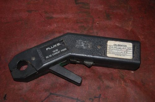
fluke y8100 AC/DC current probe works
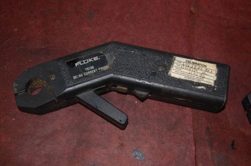
fluke y8100 AC/DC current probe works #2
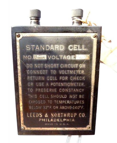
Antique Leeds & Northrup STANDARD CELL Philadelphia Lab Scientific Battery
People who viewed this item also vieved
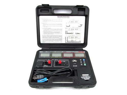
Nice Extech 380803 True RMS AC/DC Power Analyzer / Datalogger
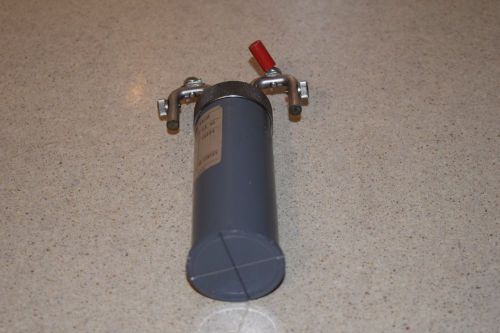
LEEDS & NORTHRUP RESISTORS 10 OHMS (B8)
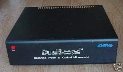
DME DualScope Scanning Probe & Optical Microscope Controller
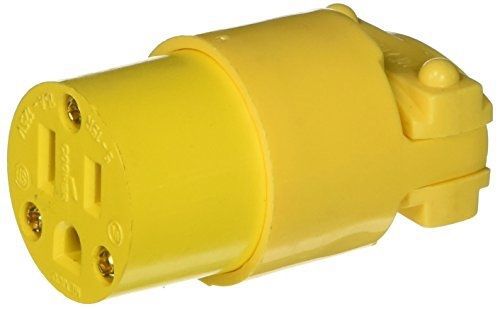
Coleman Cable 05985 Replacement Yellow Vinyl NEMA 5-15R 15-Amp Cord End, Female
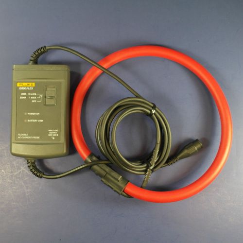
Fluke i2000 Flex AC Current Probe, Excellent condition
HP Agilent E1345-66201 E134566201 Relay Mux C
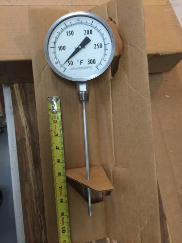
ASHCROFT BI-METAL 5" DIAL THERMOMETER 50-EI60E 9"STEM 50/300 RANGE *NSIFB
KAELUS 1900 IPA PORTABLE PIM TESTER
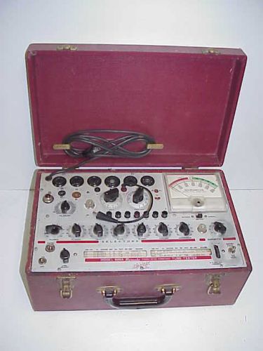
Vintage Hickok 600A Micromho Dynamic Mutual Conductive Tube Tester.
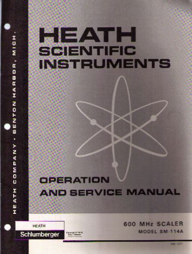
HEATHKIT Manual # SM-114A 600 MHz SCALER
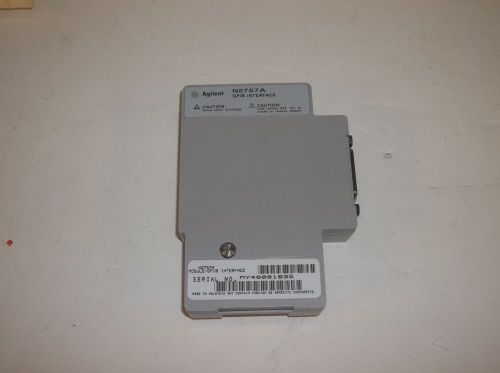
HP Agilent Keysight N2757A HPIB GPIB Interface for 5462X Megazoom Oscilloscopes
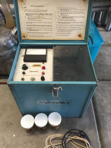
Hipotronic Portable Oil Tester Model OC60A
SMC ITV0030-2BL ITV00302BL Electro-Pneumatic Regulator U
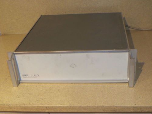
PROGRAMMED TEST SOURCES PTS 120 FREQUENCY SYNTHESIZER MODEL 120RKN (F)
Weston Vintage Amp Meter Clamp Model 633 No. 2426 Type A1 *Works* #1003
VERY NICE KROHN HITE 1 HZ TO 100 KHZ NARROW BAND TRACKING FILTER 3800
Fluke 6060B Synthesized RF Signal Generator, 30 Day Warranty
Glhstrumpf + Uranglas + Stab - Auch als Prfstrahler Geigerzhler, Gamma Scout
By clicking "Accept All Cookies", you agree to the storing of cookies on your device to enhance site navigation, analyze site usage, and assist in our marketing efforts.
Accept All Cookies