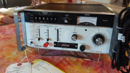
WARNING -- Any other EBay listing as "NEW" in factory wrapping is likely misleading. Units are more likely MILITARY Surplus wrapped not in original factory packaging, but in Army Depot Tobyhanna packaging after calibration and refurbishment. JUST as these units are. Use caution when purchasing these excellent signal generators as new. They were originally manufactured from 1981 thru 1984 Wavetek became Willtek Communications GmbH. www.willtek.com Then Fluke acquires Wavetek product lines from WCG in January 2000 with plan to use FLUKE badging thereafter. See company history at http://www.radiomuseum.org/dsp_hersteller_detail.cfm?company_id=7620 CONCLUSION: VERY UNLIKELY ANYONE actually has a new unit for sale, and if Military Surplus they likely came from Tobyhanna Army Depot after refurbishment and calibration -- same as my units. Compare commercial Refurbished prices trending $499 http://www.recycledgoods.com/wavetek-3001-signal-generator-1mhz-to-520mhz.html Here is a post from one of my first buyers: QUOTE FROM 47people (314) "WOW, it is like brand new!!! Almost right on in levels and freq. I would swear it was never used. It has a little noise riding on the sine wave, but I haven't used this model in over 25 years and O scopes then had no bandwidth, so I cannot say it is abnormal. Wish I could buy another. Thank you!!!!! ----Bill" Calibrated by Tobbyhanna Army Depot in late 2012, HOWEVER, May still require tuning. I've been advised by one of my buyers: QUOTE FROM 2014grvass "Due to component aging and other factors, it is expected that these devices will need frequent calibration to provide reliable testing measurements. Thank you again, take care," Find Free Instruction Manuals at: http://exodus.poly.edu/~kurt/manuals/manuals/Other/WAV%203001,3002%20Instruction.pdf http://www.ko4bb.com/manuals/index.php?dir=Wavetek/Wavetek_3001_3002 http://www.mrtestequipment.com/getfile.php?s=Wavetek+3001%2C3002+Signal+Generator+Data+Sheet.pdf The Wavetek 1170/U / 3001 is completely solid-state and rugged synthesized RF signal generator that covers the frequency range of 1 KHz to 520 MHz with 1 KHz resolution. It features internal 400 and 1000 Hz modulation tones. AM modulation range is 0 to 90%, FM deviation is variable from 0 to 10 & 0 to 100 KHz. The calibrated RF output can be varied from +13 to -137 dbm (1 v rms to .03 uv rms) with 50 watts of reverse power protection. There are vernier controls for frequency and output level, with a front-panel meter for reading output levels. It measures 12" wide x 5.25" high x 14" deep and weighs 24 lbs. Military Technical Manual TM-11-6625-3029-14 at http://radionerds.com/images/0/0c/TM_11-6625-3029-14.PDF and http://radionerds.com/images/a/ac/TM_11-6625-3029-24P.PDF Signal Generator SG-1170/U is a rugged, completely solid-state signal generator covering the frequency range of from 0.001 to 520 MHz. The output can be amplitude or frequency modulated, and the level can be set between +13 and - 137 dBm. The frequency of the instrument is set via 6 front-panel Lever/Indicator switches which yield a resolution of 1 kHz. In addition, remote frequency programmability is standard. The accuracy of the instrument is based on a crystal controlled oscillator that serves as a stable frequency reference that enables the instrument to provide high stability signals to an accuracy of 0.001% over its specified frequency range. This accuracy includes possible errors due to short term drift, long term drift, incidental FM, and variations due to line voltage changes and temperature changes. With the FREQUENCY VERNIER out of the CAL position, the frequency is accurate to 0.001% ±10 kHz. The instrument also features both internal and external amplitude and frequency modulation capabilities. Internal modulation frequencies of 400 Hz and 1 kHz are standard. In the FM mode of operation, peak deviations to 100 kHz are attainable. In the AM mode, amplitude modulation to 90% is attainable. With the MODULATION MODE switch in the AM position and the MODULATION FREQUENCY switch in the DC position, the output amplitude can be varied by the MODULATION FM/AM control. This provides a reference attenuator for variation of signal level around a specific point of interest. This operation can also enable the user to obtain greater than 20 milliwatts of power over portions of the band. The frequency can also be continuously varied with this control over a 100 kHz range. The output power is indicated on a front-panel meter calibrated in both dBm and VRMS. A fifteen-position, 10 db/step Attenuator used in conjunction with an 11 dB VERNIER control provides the user with a range of +13 dBm to -137 dBm. The calibrated output of the instrument is leveled to within ±0.75 dB across the complete frequency range of the instrument. Reverse power protection is provided. FREQUENCY SPECIFICATIONS RANGE RANGE 0.001 to 520 MHz selectable in 1 kHz steps. READOUT 6 digit Lever/Indicator switches RESOLUTION 1 kHz ACCURACY All modes (CW, AM and FM) *0.001% after 15 when FREQUENCY VERNIER is not in CAL VERNIER range is ±5 kHz.) min. (+0.001% ±10 kHz position. FREQUENCY CARRIER SHIFT <.005% for FM deviations <25 kHz STABILITY All modes (CW, AM and FM) <0.2 ppm/hour (500 Hz per 10 min. when FREQUENCY VERNIER is not in CAL position.) PROGRAMMABILITY Frequency is programmable via rear-panel coded TT L voltages or BCD-coded contact RF OUTPUT SPECIFICATIONS POWER LEVEL RANGE +13 dBm to -137 dBm (1 to .03 µVRMS) input connector using BCD closures (negative true logic). LEVEL CONTROL Continuously adjustable in 10 dB steps with an 11 dB VERNIER. Output level is indicated on a front-panel METER calibrated in volts RMS and dBm LEVEL ACCURACY Flatness (+13 to -7 dBm) ±0.75 dB Output METER ±0.5 dB Step Attenuator IMPEDANCE SWR < ±0.2 dB/10 dB step (±0.2 dB calibration error) 50 ohms <1.25 at RF output levels below 0.1 VRMS OUTPUT CONNECTOR Type N RFI LEAKAGE <1 µV is induced in a two-turn, one-inch diameter loop which is held one inch away from any surface. Loop feeds a 50 ohm receiver. 1.2.4 SPECTRAL PURITY HARMONIC OUTPUT <-30 dBc from 10 to 520 MHz and 1 kHz to 1 MHz <-26 dBc from 1 to 10 MHz SUB-HARMONICS NON-HARMONICS None detectable Fundamental Non-Harmonic Non-Harmonic (MHz) (MHz) Level (dBc) below 3 below 3 <-60 3 to 250 3 to 250 <-65 3 to 350 3 to 350 <-55 3 to 520 3 to 1000 <-35 RESIDUAL AM FM INCIDENTAL AM RESIDUAL FM <-65 dBc in a 50 Hz to 15 kHz post-detection bandwidth. < 1% for FM deviation of 40 kHz <200 Hz in 50 Hz to 15 kHz post-detection bandwidth. <100 Hz in 300 Hz to 3 kHz post-detection bandwidth. SSB PHASE NOISE FLOOR NOISE AMPLITUDE MODULATION <-100 dBc/Hz at 20 kHz offset from carrier <-115 dBc/Hz at 500 kHz offset from carrier NOTE: These specifications apply for a carrier level <+3 dBm. AM is possible above +3 dBm if the peak output does not exceed +13 dBm. FREQUENCY Internal 400 Hz and 1 kHz ±5% External DC to 20 kHz, (3 dB bandwidth). Input level required = 5 Vpp into 600 ohms to provide calibrated % modulation control. RANGE 0 to 90% DISTORTION 0 to 30% AM, <2% 30 to 70% AM, <3% 70 to 90% AM, MODULATION CONTROL Calibrated from 0 to 90% Accuracy ± (5% +5% of reading) at a frequency of 1 kHz FREQUENCY MODULATION FREQUENCY Internal 400 Hz and 1 kHz, External 50 Hz to 30 kHz. (DC to 25 kHz when FREQUENCY VERNIER is not in CAL position.) Input level required = 5 Vpp into 600 ohms to provide calibrated deviation control. (Voltage required for 10 kHz deviation from 100 Hz to 15 kHz varies <± 10% from voltage required at 1 kHz. Voltage required for 10 kHz deviation from 15 to 30 kHz varies < ±20% from voltage required at 1 kHz.) DEVIATION PEAK Two bands, 0 to 10 kHz, and 0 to 100 kHz DEVIATION CONTROL Calibrated from 0 to 10 kHz, x1 and x10 Accuracy 500 Hz on x1 range ±5 kHz on x10 range DISTORTION <2% (10 kHz to 100 kHz deviation) at a frequency of 1 kHz. <4% (3 kHz to 10 kHz deviation) at a frequency of 1 kHz. REVERSE POWER PROTECTION This circuit prevents damage to the instrument if RF (0.7W max) or DC (72.5 V max) voltages are accidentally applied to the RF OUT connctor. GENERAL OPERATING TEMPERATURE 25° C ±5° C, all specifications apply 25° C ±15° C, with slight degradation of specifications POWER 100, 120, 220 or 240 VAC ± 10%; 45 to 440 Hz, 100 VA max DIMENSIONS 30.3 cm wide x 13.4 cm high x 34.9 cm long (12” x 5-1/4” x 13-3/4”). WEIGHT 11.4 kg (24 lb)
By clicking "Accept All Cookies", you agree to the storing of cookies on your device to enhance site navigation, analyze site usage, and assist in our marketing efforts.