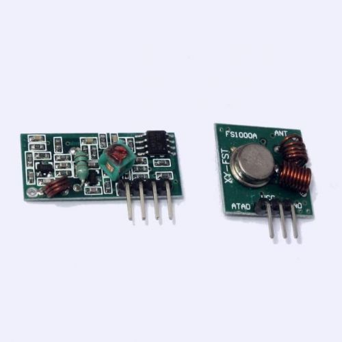
Spend $10 and Shipping is FREE ! Delivery time: USA ~1wk, Canada ~1-2wk, World 2-6wk. Buy multiple items in single order and pay first item shipping only, other items SHIP FREE* or with discount. See below how it works. How combined ship works: press Add To Cart and then pay for all items in single payment creating one order. Multiple payments will result in multiple orders and multiple shipments. No adding after payment, please make new order. Why we have such policy? Because order was already sent to fullfilment and even if not shipped, it was most likely processed. Adding disrupts processing workflow, order has to be located and repacked. Thank you for understanding. Sale is for 1pair, if you need different quantity, search our store for DE4220. Code DE4220 Lot Size 1 pair Manufacturer Generic Receiver Model: MX-05V Working voltage: 5V DC Quiescent current: 4mA Receiver Frequency: 315MHz Receiver sensitivity: -105DB Dimensions: 30 x 14 x 7mm Pinout: Pin1=Antenna (left side lone pin), Pin2=VCC, Pin3=DataOut, Pin4=DataOut, Pin5=GND Transmitter Transmitter Model: MX-FS-03V Transmission Distance :20-200 m (dependent on supply voltage) Operating Voltage :3.5-12V Dimensions: 19 x 19mm AM transfer rate: 4KB / S Transmission power: 10mW Emission frequency: 315MHz Pinout: Pin1=DataIn, Pin2=VCC, Pin3=GND Notes When using an external antenna a 1/4 wavelength is recommended. Ideally use 50 impedance ohm single-core wire, the length of the antenna 433M is about 17cm (1/4 wavelength). When locating the receiver antenna keep it as far away as possible from shielded areas, high voltages, and any other possible interfering frequencies. APPLICATIONS: Remote control switch, receiver module, motorcycles, automobile anti-theft products, household anti-theft products, electric doors, shutter doors, windows, remote control socket, remote control the LED, remote control stereo, remote control electric gate, garage door remote control, remote control retractable doors, remote control volume gate, pan doors, remote control door opener, door closing device control system, remote control curtains, alarm system, alarm, remote control motorcycle, remote control electric cars, remote control such as MP3. Programming Examples VirtualWire Library Example AVR Project ARDUINO TRANSMIT EXAMPLE /* FILE: MXFS03V_433MHZ_MODULE_HCMODU0007_TRANSMIT_EXAMPLE.pde DATE: 03/03/13 VERSION: 0.1 AUTHOR: Andrew Davies This is an example of how to use the 433MHz wireless transmitter module (HCMODU0007) which is the Tx part of the tranmitter and receiver module pair. This example makes use of the VirtualWire library written by Mike McCauley. The sketch will read a value from the analogue input A0 and transmit it as 2 bytes to the receiver module once every second. Tx MODULE CONNECTIONS: PIN DESCRIPTION ARDUINO PIN 1 GND GND 2 VCC (3.5-12V) VCC 3 TX DATA D2 You may copy, alter and reuse this code in any way you like, but please leave reference to HobbyComponents.com in your comments if you redistribute this code. THIS SOFTWARE IS PROVIDED "AS IS". HOBBY COMPONENTS LTD MAKES NO WARRANTIES, WHETHER EXPRESS, IMPLIED OR STATUTORY, INCLUDING, BUT NOT LIMITED TO, IMPLIED WARRANTIES OF MERCHANTABILITY AND FITNESS FOR A PARTICULAR PURPOSE, ACCURACY OR LACK OF NEGLIGENCE. HOBBY COMPONENTS SHALL NOT, IN ANY CIRCUMSTANCES, BE LIABLE FOR ANY DAMAGES, INCLUDING, BUT NOT LIMITED TO, SPECIAL, INCIDENTAL OR CONSEQUENTIAL DAMAGES FOR ANY REASON WHATSOEVER. */ /*Include the VirtualWire library */ #include /* Digital IO pin that will be used for sending data to the transmitter */ const int TX_DIO_Pin = 2; void setup() { pinMode(13, OUTPUT); /* Initialises the DIO pin used to send data to the Tx module */ vw_set_tx_pin(TX_DIO_Pin); /* Set the transmit logic level (LOW = transmit for this version of module)*/ vw_set_ptt_inverted(true); /* Transmit at 2000 bits per second */ vw_setup(2000); // Bits per sec } /* Main program */ void loop() { /* Temporarily holds the value read from analogue input A0 */ unsigned int Data; /* The transmit buffer that will hold the data to be transmitted. */ byte TxBuffer[2]; /* Read the analogue input A0... */ Data = analogRead(A0); /* ...and store it as high and low bytes in the transmit buffer */ TxBuffer[0] = Data >> 8; TxBuffer[1] = Data; /* Turn on the LED on pin 13 to indicate that we are about to transmit data */ digitalWrite(13, HIGH); /* Send the data (2 bytes) */ vw_send((byte *)TxBuffer, 2); /* Wait until the data has been sent */ vw_wait_tx(); /* Turn off the LED on pin 13 to indicate that we have now sent the data */ digitalWrite(13, LOW); /* Do nothing for a second. Lower this delay to send data quicker */ delay(1000); } ARDUINO RECEIVE EXAMPLE /* FILE: MX05V_433MHZ_MODULE_HCMODU0007_RECEIVE_EXAMPLE.pde DATE: 03/03/13 VERSION: 0.1 AUTHOR: Andrew Davies This is an example of how to use the 433MHz wireless reciever module (HCMODU0007) which is the Rx part of the tranmitter and reciver module pair. This example makes use of the VirtualWire library written by Mike McCauley. This sketch in intended to be used with the Tx example code to recive analogue input data sent from the transmitting Arduino. The received data is then output to the UART. Rx MODULE CONNECTIONS: PIN DESCRIPTION ARDUINO PIN 1 GND GND 2 RX DATA D2 3 RX DATA N/A 4 VCC (5V) VCC You may copy, alter and reuse this code in any way you like, but please leave reference to HobbyComponents.com in your comments if you redistribute this code. THIS SOFTWARE IS PROVIDED "AS IS". HOBBY COMPONENTS LTD MAKES NO WARRANTIES, WHETHER EXPRESS, IMPLIED OR STATUTORY, INCLUDING, BUT NOT LIMITED TO, IMPLIED WARRANTIES OF MERCHANTABILITY AND FITNESS FOR A PARTICULAR PURPOSE, ACCURACY OR LACK OF NEGLIGENCE. HOBBY COMPONENTS SHALL NOT, IN ANY CIRCUMSTANCES, BE LIABLE FOR ANY DAMAGES, INCLUDING, BUT NOT LIMITED TO, SPECIAL, INCIDENTAL OR CONSEQUENTIAL DAMAGES FOR ANY REASON WHATSOEVER. */ /*Include the VirtualWire library */ #include /* Digital IO pin that will be used for receiving data from the receiver */ const int RX_DIO_Pin = 2; void setup() { pinMode(13, OUTPUT); Serial.begin(9600); /* Initialises the DIO pin used to receive data from the Rx module */ vw_set_rx_pin(RX_DIO_Pin); /* Receive at 2000 bits per second */ vw_setup(2000); /* Enable the receiver */ vw_rx_start(); } /* Main program */ void loop() { /* Set the receive buffer size to 2 bytes */ uint8_t Buffer_Size = 2; /* Holds the recived data */ unsigned int Data; /* The receive buffer */ uint8_t RxBuffer[Buffer_Size]; /* Has a message been received? */ if (vw_get_message(RxBuffer, &Buffer_Size)) // Non-blocking { /* If so, then turn on the LED connected to DIO 13 to indicate this */ digitalWrite(13, HIGH); /* Store the received high and low byte data */ Data = RxBuffer[0]
By clicking "Accept All Cookies", you agree to the storing of cookies on your device to enhance site navigation, analyze site usage, and assist in our marketing efforts.