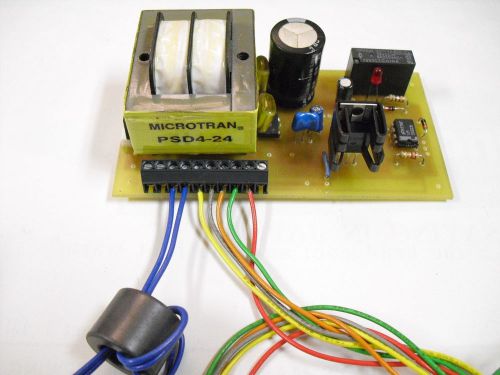
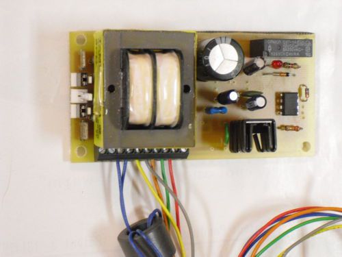
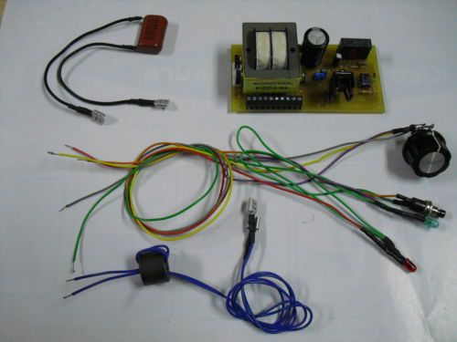
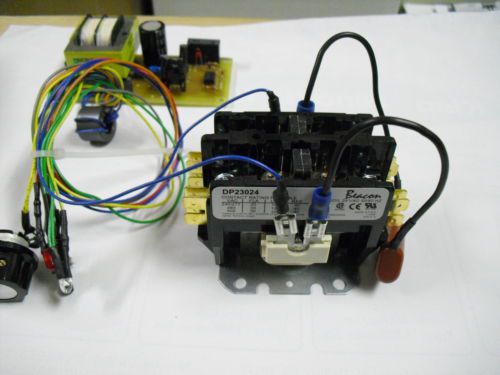
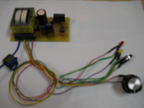
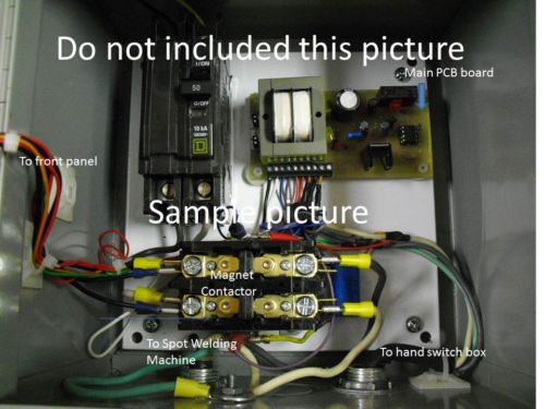
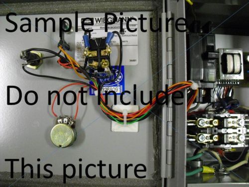
Click Here. Double your traffic. Get Vendio Gallery - Now FREE! 0-6 Second Spot Welding Timer KIT 7.2KVA/240V,3.6KVA/120V (main PCB with control wire) When you sold it, I will set up for your requested voltage. 0 ~ 6 second timers, primary power 120V or 240V (by select jumper), power indicator You should use your control box or separate box and breaker. (show at the sample picture) How to use; 1 Connect your spot welder after Spot Welding Timer controlled Magnet contactor(Spot welder power turn on state)--- it is state of SWT timer controlled 2 Set up time by potentiometer (0 – 6 second) 3 Check power indicator on (LED indicator on) 4 Clump on welding items by Spot welder 5 Push on Timer Start Switch (red LED indicator on) How to change supply power 240V/120V ;( when ship 120V setting) 120V setting ---use two jumper at side of A and C(remove one 240V jumper) Power wire connect to terminal #1 & #2 240V setting ---use one jumper at center of jumper B(remove two 120V jumper) Power wire connect to quick disconnect(TAB) connector Included: Power indicator, Welding indicator, Timer start switch, Potentiometers, Main board, 7-wires, Suppressor with magnet contactor. 0 ~6 second label sign, Potentiometer with knob, Spot Welding Timer Sign. (2)240V power supply wire for PCB, (4)Teflon 3mm screw with spacer, Instruction Not included: Breaker 50A, 240V,2pole Main power wiring supply & secondary 240V or 120V receptacle Enclosure box Extra ; Switch hand box ------------------------------------------------------------------------------------------------ INSTRUCTION for Spot Welding Timer Kit Part included; Power indicator, Welding indicator, Timer start switch, Potentiometers, Main board, 7-wires, Suppressor and ferrite core with magnet contactor. 0 ~6 second label sign, Potentiometer with knob, Spot Welding Timer Sign. (2)240V power supply wire for PCB, (4)Teflon 3mm screw with spacer, Instruction Not included; Breaker 50A, 240V,2pole Main power wiring (supply & secondary) 240V or 120V receptacle(or direct connect) Enclosure box Super Glue 3mm tap, 2.6mm drill, screw driver, (install PCB) 4mm tap, 3.6mm drill, 4mm screw (install MC) 5mm, 6.2mm, and 6.8mm drill (front of panel) Extra, Switch hand box Output Receptacle or Cable ----------------------------------------------------- 1) Install Main PCB (printed circuit board) Make (4) holes at your box bottom or base plate (2.6mm size on the place of 42mm x 92mm) Make (4) tapping on the holes, then install PCB by Teflon screws with Teflon spacer to bottom, 2) Install Magnet Contactor to your box Make (4 holes at your box bottom or base plate (3.6mm size on the place of 41mm x 41mm) Make (4) tapping on the holes, then install Magnet Contactor by your 4mm metal screws) 3) Install Switch, Indicators, and Potentiometer on the front of your box. Make (2) 5mm holes for Indicators (use your super glue at edges hole) Make (1) 6.2mm hole for Switch (tie by attached nut) Make (1) 6.8mm hole for potentiometer (have to have space around 35mm- top, bottom, right and left for label. 4) Install your Breaker (or Fusible Disconnect) to your box. Connect power supply wire to breaker or disconnect. Connect breaker secondary wire to PCB board and Magnet Contactor primary. CHECK PCB board jumper for supply voltage. 120V setting ---use two jumper at side of A and C(remove one 240V jumper) 240V setting ---use one jumper at center of jumper B(remove two 120V jumper) Power wire connect to quick disconnect(TAB) connector (both of 120V & 240V) 5) Install control wiring. PCB terminal to 7wires. (when ship at all wiring connection to terminal - need tie up & check) 3,4 – MC; 5,6 - Potentiometer, 7 - Switch, 8 - common, 9 – indicator Install Suppressor between both terminal of magnet contactor coil.(with 3 & 4 wire) 6) Install secondary wire at between Magnet Contactor and connect your Receptacle or Cable. You should connect the quick disconnect terminal at Magnet Contactor. If you use the Extension Cable and Receptacle, make sure it same type as your Spot Welder. 7) Test and Inspection of Spot Welding Timer. Make sure all terminal connection ties. Quick Connector all tie. Do not have any metal trash in the box. Supply Voltage and PCB voltage same (jumper setting same) Do not connect Spot Welder. Supply Power Breaker (or disconnect) turn on. – Power Indicator light up! (if not, cut power and check wiring) If it light up go to next. Set 1 second then push on Timer Switch – Red Indicator light up and Magnet Contactor start. If it working okay, next set to 6 second then push on Timer Switch, (check noise and vibration) Next Connect Spot Welder and it on state then use Spot Welder and Timer. IF YOU THINK DIFFICULT FOR ASSEMBLE KIT, WE SELL THE COMPLETE MACHINE AT E-BAY. 240V testing https://www.youtube.com/watch?feature=player_detailpage&v=6Vb9sRtZe5k 120V testing https://www.youtube.com/watch?feature=player_detailpage&v=lU7ZvD4Beyw ---------------------------------------------------------------------------------------------------------- Spot Welding Timer (Questions) ---------------- Will this unit work with a 220VAC Miller Spot Welder? ; Do you off instructions with the kit? A bill of materials to enclose it? Does it work by sensing current when welding process is started by built in switch and then disconnects power after time set has passed. Also does it control power source only and does not connect to the internal of the welder. (Answer) -------------------- What KVA for Miller Spot Welder?—spot welding timer have limit current by magnet contactor, It include the instruction. It include the General Purpose Magnet Contactor (30A, 2pole) You should connect receptacle (you supply), does not touch inside welder, from your power source to connect breaker (or disconnect) then connect to main timer board (include) & magnet contactor (include), after magnet contactor connect to receptacle (you supply- same type of welding machine or just connect welding machine cable) You need know how many second welding. Then set up the Spot Welding Timer. 1, Clamp the object (welding items) and welding machine turn on, 2, Connect welding machine to your receptacle or magnet contactor (after SWT timer), 3, Set up to welding time by potentiometer (0 ~ 6 second by the SWT timer) (include potentiometer and second label) 3, Start switch push on for SWT timer, (use hand switch box- convenient) (include switch and indicator) 4, Red indicator turned on and start timer then stop automatic, FREE! Sellers: Add a FREE map to your listings. FREE!
By clicking "Accept All Cookies", you agree to the storing of cookies on your device to enhance site navigation, analyze site usage, and assist in our marketing efforts.