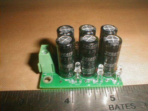
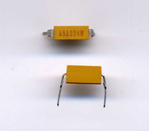
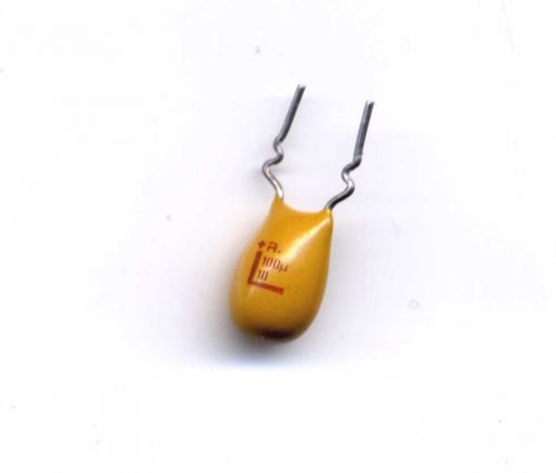
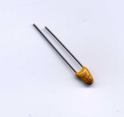
Ultracapacitor 1.33F SixPack Module Kit You are bidding on an ultracapacitor battery elimination module kit. It consists of six 8 farad 2.7 volt ultracapacitors, one printed circuit board six 1N914 diodes, one 1N966 zener diode, 6 yellow T1 LEDs, six yellow insulating stickers, and one 2 position connector The LEDs and diodes comprise 6 individual balancing sections, one per ultracap. This is a much smaller version of our 350F kit, also available from us on ebay. Assembly: Assembly is pretty simple. The board silkscreen shows where to place the components. The ends of the 1N914 diodes and 1N966 zener the with the cathode stripes go in the square holes, and the short leads of the LEDs go in the square holes. The positive lead of ultracaps go in the square holes. The connector goes in its holes with the wire entry holes facing away from the ucaps. You should probably install the LEDs so they stick up 1/2 inch or so to be sure they are far enough away from the hot solder so they won't be damaged. Install the diodes and LEDs first, then with your multimeter set on diode check, verify that they are not backwards or damaged. If you have to remove one of them, it is much easier to do before the ultracaps are installed next to them. Here is a video of someone who copied the schematic and made an 8 ultracap bank. CLICK HERE TO SEE IT. He demonstrates the circuit and explains it pretty well. And HERE is another article about large and small ultracaps and their uses. And HERE is a paper about charging ultracaps. A little technical, but useful information. WHAT YOU GET: 6 Tecate Group 8 Farad ultracapacitors 1 Printed Circuit Board (PCB), 4 oz copper 7 1N914 diodes (1 spare) 1 1N966 16V zener diode 7 yellow T1 ultrabright LEDs (1 spare) 1 2 position high current screw connector Physical specs of assembled module: Length 2”(50mm) Width 1.3” (33mm) Height 1.1” (28mm) Weight 1 oz (30gm) Here is a writeup on the completed module: ------------------------------------------------------------------------------------------------ Ultracapacitor 8F SixPack Module This module consists of six 8 farad 2.7 volt ultracapacitors connected in series and includes a cell balancing circuit to keep the voltages on the individual ultracapacitors balanced. The total module capacitance is 1.33 farads, and the max voltage is 16.2 volts DC If fully charged, the stored energy is 175 joules, which is 175 watt-seconds, or .05 watt-hours. The balancer section contains six super efficiency yellow LEDs and silicon diodes which leak small amounts of current from any ultracapacitor in the module if it is charged to near its voltage limits. Incidentally, the LEDs give a rough indication of the module state of charge. The brighter the LED, the higher the state of charge. The current drain of the balancer is very low unless the module is near full charge, so the energy loss is negligible in most applications. If the module voltage is not over 12 volts or so there is basically no energy loss even after months of storage. There is a 16V zener diode across the bank to limit the total module voltage to 16v or less. However, it it only rated 1/2 watts, so if your power source can supply much more than about 30 mA at 16V, it may destroy the zener from too much power. If you are charging the module with a low current source like a small solar panel, the zener will protect the module from overvoltage. The module is rated 16.4 volts maximum. Application Examples: Car Audio Systems High performance audio systems often require more power from the battery for brief periods than the battery and associated cabling can deliver. This results in clipping and distortion in the sound output during audio peaks. The module can be connected across the power leads as close as possible to the amplifier to deliver high current for those times when it is necessary, resulting in crisp clean audio output at all times. Battery life extension Batteries can store large amounts of electrical energy, but are generally not good at delivering the stored energy rapidly. An ultracapacitor module has lower energy storage capacity, but can discharge its stored energy very rapidly and efficiently. Battery life is adversely affected by short discharge bursts, which can rapidly damage the battery electrode structure. If an ultracapacitor module is connected in parallel with a battery, the battery can handle the steady absorption and delivery of electrical energy while the module takes care of the short high power bursts as necessary. This can result in dramatically increased battery and system lifetime. . Remote Equipment Monitoring Oil and gas industry remote production installations often require automated monitoring, often solar powered. Such applications monitor the equipment status and periodically transmit wireless status updates. Ultracapacitor modules can often completely replace the lead acid batteries typically used in such applications. The -40 to +70 deg C (-40 to +158 deg F) temperature rating ensures trouble free operation in all climates Emergency Backup Power In an emergency, power to vital systems may be lost. This can be avoided by locating an ultracapacitor bank near the essential equipment to supply the necessary power in the event of a power loss. For example, passenger aircraft emergency exits have ultracapacitor backups in case of an emergency where power to the door mechanism would be otherwise be lost. Bus Voltage Stabilization Electronic systems can have voltage sags and spikes due to short term power demands from brief loads such motor starting surges. Ultracapacitors placed near critical subsystems can keep such sags and spikes from disrupting subsystem operation. This module has the balancing circuitry included on the board between the six ultracapacitors. The connector will accept up to #14 wire. When installing wire in the connector, first turn the screw counterclockwise until the connector is fully open. Look into the wire entry hole so you can see how it operates. Then insert the wire and tighten the screw clockwise until the wire is tightly secured. There is also provision to directly solder a #10 wire into the circuit board, plus provision to connect a wire terminal to the board with a #6 size screw. The module is intended to be part of larger electronic assemblies, so it has no other enclosure. You will likely want to protect the circuit board from accidental contact with metal conductors. You can mount it in some kind of box or enclosure, or just cover the module with a some electrical tape or similar. You can check out our other ultracapacitors and related stuff HERE. All our ebay listings have links to useful information and websites. What you get: What it should look like when you are done: Electrical schematic: Buyers pay all shipping duty taxes.
By clicking "Accept All Cookies", you agree to the storing of cookies on your device to enhance site navigation, analyze site usage, and assist in our marketing efforts.