
US $89.88
| Condition: |
New: A brand-new, unused, unopened, undamaged item in its original packaging (where packaging is
applicable). Packaging should be the same as what is found in a retail store, unless the item was packaged by the manufacturer in non-retail packaging, such as an unprinted box or plastic bag. See the seller's listing for full details.
...
|
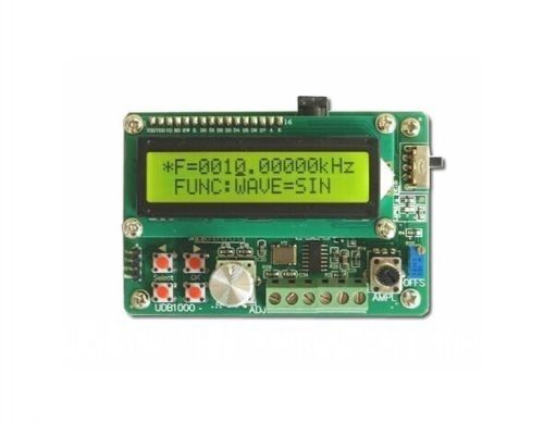
Positive and negative pulse width length | 0.000s-9999s. The minimum can be set 1ms |
| MPN | Does Not Apply | ||
| Output Current | Less 8A(MOS Switch) | ||
| Brand | Unbranded | ||
| Output amplitude | amplitude is equal to supply voltage | ||
| Working voltage | 3.3~30V (Reverse connection is not allowed) | ||
| Product size | 60*32*13.5mm | ||
| Frequency range | 1Hz~150KHz, accuracy about 2%. Motor speed is gene | ||
| Model | PWM Pulse Frequency | ||
| Duty cycle range | 0-100%, 1% stepping | ||
| Modified Item | No | ||
| Number of pulses | 1-9999, or infinite (---- displayed stands for inf | ||
| Country/Region of Manufacture | China | ||
| Delay output time | 0.000s-9999s.The minimum can be set 1ms | ||
| Custom Bundle | No | ||
| UPC | Does not apply |
Directions
Similar products from Other Signal Generating Equipment

Koolertron Upgraded 15MHz DDS Signal Generator Counter,High Precision Dual-Ch...

Current Voltage Signal Generator 0-5V-10V 0-4-20mA Analog Constant Current Sourc
1HZ-500KHz DDS Function Signal Generator Sine+Triangle + SUSB to DC Power Cable

Vintage RCA No.154 Beat-Frequency Oscillator

HP Agilent 83640A 10 MHz - 40 GHz Synthesized Sweeper Option 004 008
Novellus Systems 03-00288-02 RF Cable Coax CA57 36 Foot New Surplus

USED Logic Innovations TSM-1000A Multiplexer Transport Stream MUX Rack Unit

VHF SYNTHESIZER TESTER PN: 599-0002-075

AD9833 DDS Signal Generator Module Waveform Frequency Low Pass Filter

5PCS Dual Mode LCD Adjustable PWM Pulse Frequency Signal Generator Module Duty

DC Amplifier Power Module Maximum Output 10W For DDS Function Signal Generators
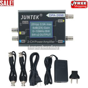
DPA-2698 2-CH Function Generator Amplifier 0-10KHz 5W*2 for DDS Signal Generator

Koshin Kogaku LS-601A Super Fine Resolution Tunable LD Light Source
HP 81532A Power Sensor module 800-1700nm

FPA0510S DC Amplifier Power Maximum Output 10W For DDS Function Signal Generator

FYE050 DDS Function Signal Source Generator 1W Output 3V Random Waveform Module

Teledyne LeCroy WS3K-MSO Mixed Signal probe for WaveSurfer 3000
Adret 740A UHF Generator 0.1 / 1120 MHz, Damaged hs
Trazar 62339-001 H/F RF Box Novellus Systems 19-162063-00 OEM Refurbished

HP 200CD Wide Range Oscillator - Used / Working - ILI: 88
People who viewed this item also vieved
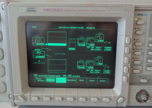
SONY TEKTRONIX AWG 2020 ARBITRARY WAVEFORM GENERATOR WITH RACK MOUNT
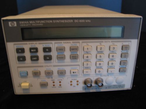
HP-8904A Signal Gemerator Option 006 H16 600 ohm non working
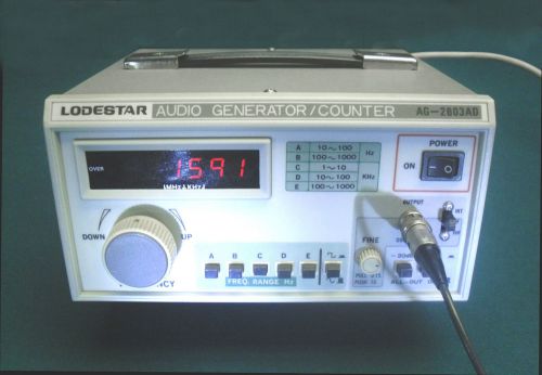
Digital Audio Signal Generator / Counter, 10Hz to 1MHz, AG-2603AD, (Quantity 1)
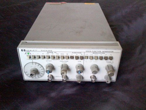
HP Hewlett Packard 3312A Function Generator, powers up, green led! Should work!
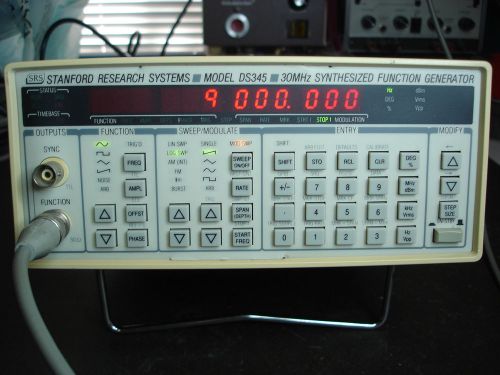
Stanford Research Systems Model DS345 30MHz Synthesized Function Generator
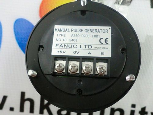
New Fanuc A860-0203-T001 MPG Manual Pulse Generator Handwheel A8600203T001
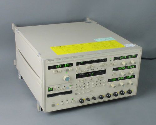
Anritsu MP1652A Pulse Pattern Generator 0.05 MHz to 3 GHz w/ Cal Certs
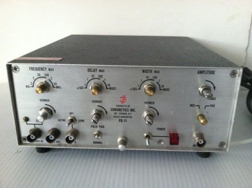
Chronetics Model PG11 Pulse Generator *** Free Shipping
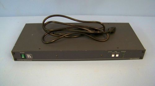
Kramer VM-4HDCP 1:4 DVI Distribution Amplifier
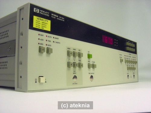
HP Agilent 8130A 300 MHz Fast Pulse Generator Calibrated w/ Certification
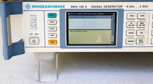
Rohde & Schwarz SMA100A -B22-B103-B81 9 kHz to 3 GHz Signal Generator
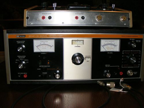
B&K 1040 CB Service Master and B&K 2040 CB Signal Generator
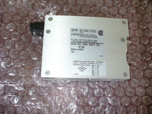
Moore Industries SIX Signal Isolators,
DDS Function Signal Generator Source With 60MHz Frequency Counter DDS Module 2MH
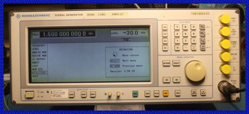
Rohde & Schwarz SMIQ-03 Signal Generator / 300 kHz - 3.3 GHz / No Errors!
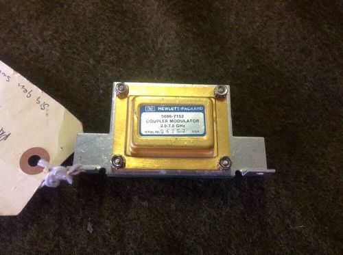
Hp Coupler Modulator 5086-7152 For 86290 Sweeper
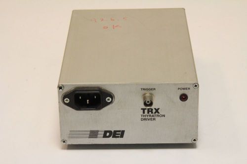
DIRECTED ENERGY TRX PULSE MODULE (#46-AT)
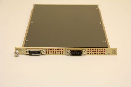
DSP TECHNOLOGY IO-612, IO612 DUAL I/O REGISTER MODULE (#46AT)
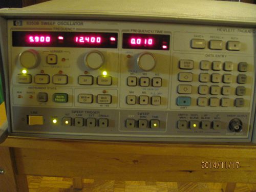
HP 8350B SWEEP OSCILLATOR MAIN FRAME
By clicking "Accept All Cookies", you agree to the storing of cookies on your device to enhance site navigation, analyze site usage, and assist in our marketing efforts.
Accept All Cookies