


US $33.18
| Condition: |
New: A brand-new, unused, unopened, undamaged item in its original packaging (where packaging is
applicable). Packaging should be the same as what is found in a retail store, unless the item is handmade or was packaged by the manufacturer in non-retail packaging, such as an unprinted box or plastic bag. See the seller's listing for full details.
...
|
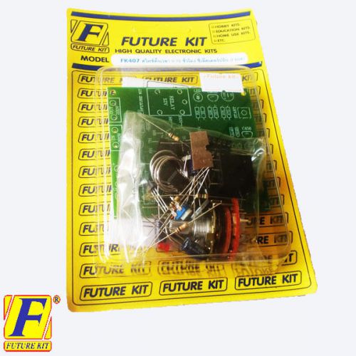
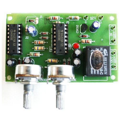
Brand | Future Kit |
| MPN | FK407 | ||
| Model | FK407 | ||
| Country/Region of Manufacture | Thailand | ||
| UPC | Does not apply |
Directions
Similar products from Timers, Time Switches & Timer Relays
OMRON H3DK-M1 Multifunction Timer Relay NEW
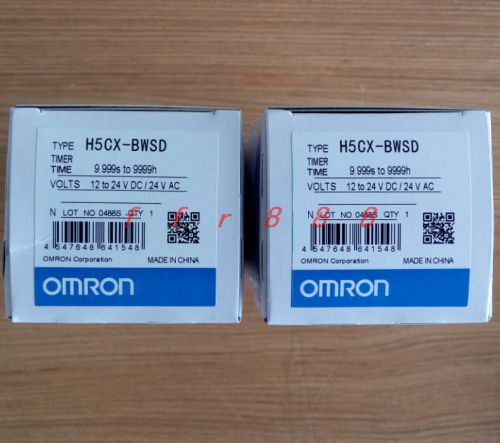
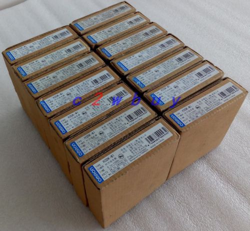
Omron H5CX-BWSD H5CXBWSD Timer 12~24VDC/24VAC NEW in box
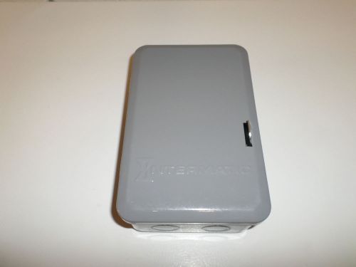
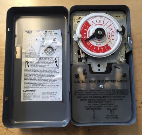
NEW Intermatic T103 Mechanical Time Switch
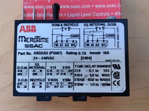
ABB MICROTIME ASQUA3 TIMER TIMING MODULE INTERVAL RELAY
Digital LCD Programmable Timer Switch THC 15A DC 110V AC 220V New HC
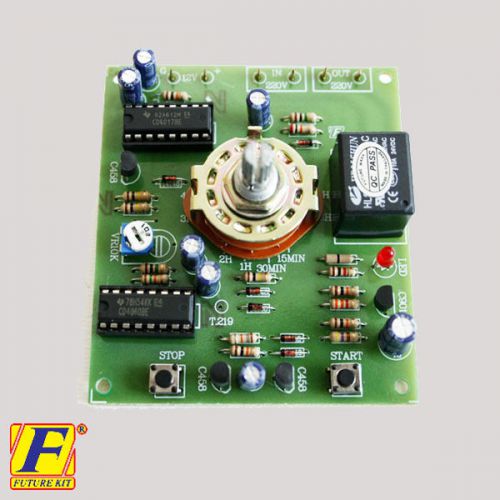
2x FA407 TIMER SWITCH OFF RELAY DELAY 15MINUTE TO 10HR,CIRCUIT BOARD,ASSEMBLED K
NEW DANAHER MP3A63101 6 SECOND - 36 HOUR 120/240V-AC TIMER D511381
2x FA432 SWITCH ON-OFF CIRCULATED 1-180 MIN,TIMER DELAY RELAY CYCLING,ASSEMBLED
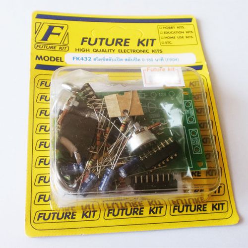
2x FK432 SWITCH ON-OFF CIRCULATED 1-180 MIN,TIMER DELAY RELAY CYCLING, UN-ASSEMB
2x MXA105 TIMER DELAY OFF SWITCH,1-120 MINUTE,ELECTRONIC CIRCUIT BOARD,ASSEMBLED
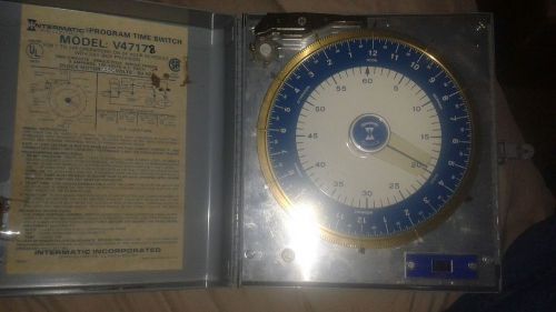
VINTAGE -PROGRAM TIME SWITCH by INTERMATIC. MECHANICAL GEARS /ELECTRIC ALL METAL
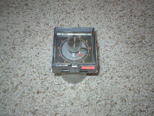
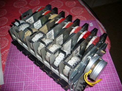
EAGLE SIGNAL 0-10 HOURS CYCL-FLEX PANEL MOUNT TIMER HP59A601
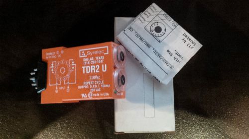
NEW - Syrelec / Crouzet TDR2U-100V Timer
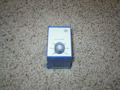
ATC 322B MOTOR DRIVEN TDR 0-60 MIN. MINUTE TIMER
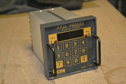
Incoe Dual Phaser T-100 Timer Control
ITC H-15 INDUSTRIAL TIMER 15 SECONDS 120 VAC 10 AMP autotrol
Paragon 4004-71 General Timer Switch
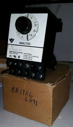
Eagle signal control BR19A6 120V 50/60HZ 6G94
A-878-20 Paragon 208-240Volt Drive Module + 8 A-876-99 Program RM Hour Modules.
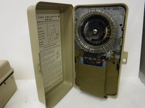
8007 Tork Time Program Switch Time Clock 8007 with Omitting Device NOS
People who viewed this item also vieved
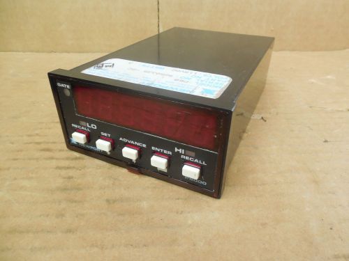
REDINGTON 9520-221 Microprocessor based controller
CK Kuebler MK16.21/ Kubler Mk16.21 Pulse Counter
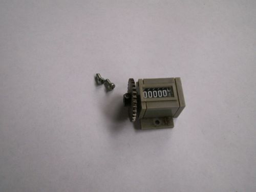
Vintage Veeder Root Solid Heavy Brass Elm City Counter Mechanical 5 digit
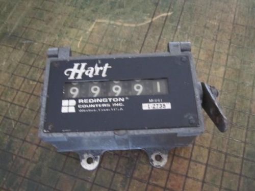
Hart Redington Counters Inc. Mechanical Counter Model 1-2735 - Works Good
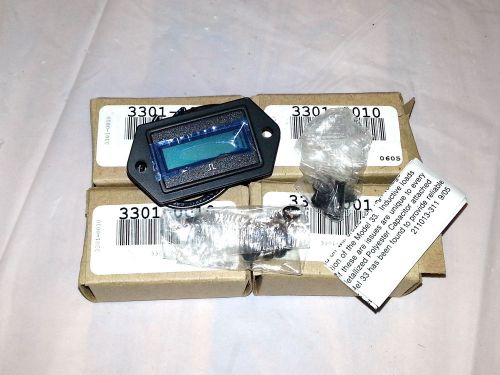
Lot of 4 NEW REDINGTON 3301-0010 REMOTE RESET COUNTER 3301
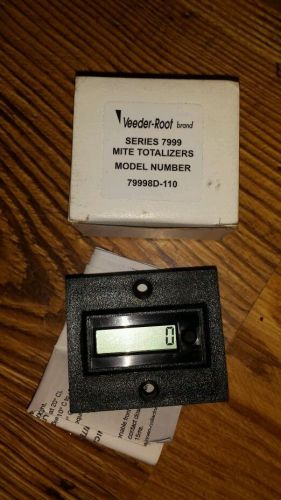
Veeder Root 79998D-110 Digital totalizer
REDINGTON 115VAC 8W 6-DIGIT COUNTER, P32-1026
Newport P6000 Digital Panel Meter Counter P60 115 VAC 3 Watt Used
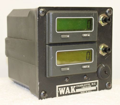
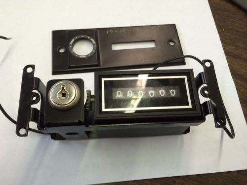
WAK Industries CA5300-402 CA-5300 Counter **XLNT**
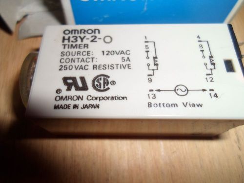
OMRON H3Y-2-0 TIMING RELAYS (NEW IN BOX)
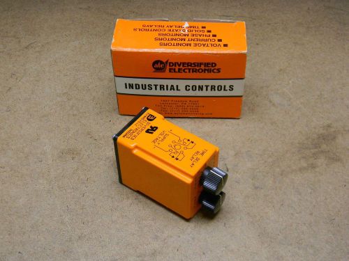
Diversified Electronics TDF-120-AKA-060 Time Delay Relay Repeat Cycle 120 VAC/DC
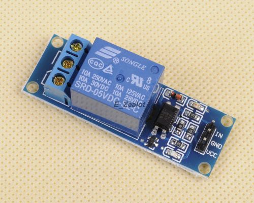
5V 1-Channel Relay Module with Optocoupler High Level Triger for Arduino J
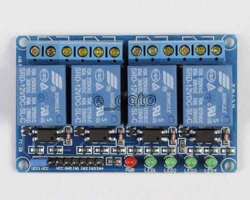
12V 4-Channel Relay Module with Optocoupler High Level Triger for Arduino Raspbe
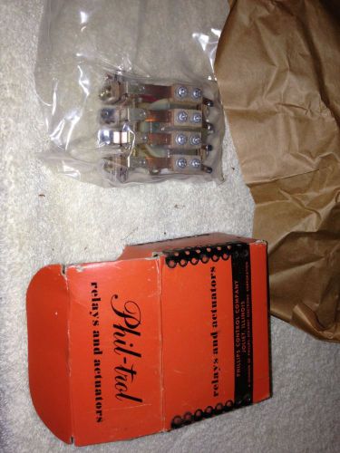
Phil -Trol Electric PC4C Relay. 115VA

SQUARE D Overloads (group of 4 sold together)
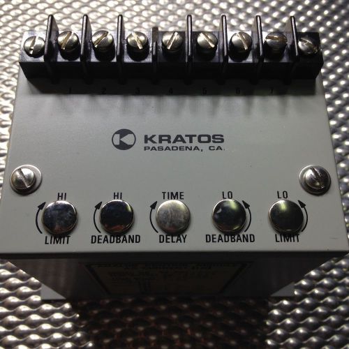
Kratos Analog Control AC Relay, Model no.85.401, 85.401-ACBC, 0-10amps *NSNB
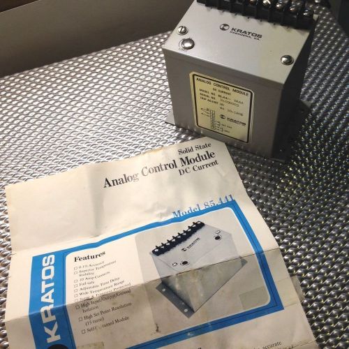
Kratos Analog Control DC Relay, Solid State, Model no.85.441, 85.441-DAAA *NSNB
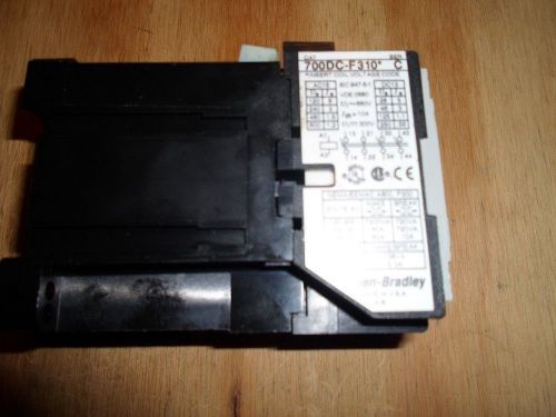
ALLEN BRADLEY 700DC-F310* CONTROL RELAY 24VDC COIL (NEW / UNUSED)
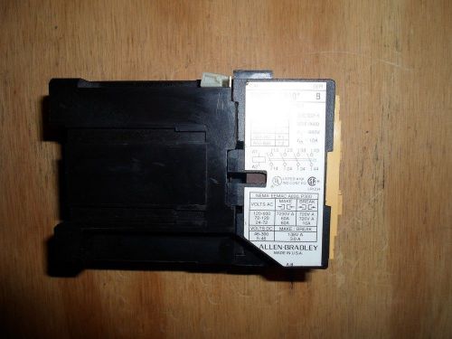
ALLEN BRADLEY 700DC-F400* CONTROL RELAY 24VDC COIL (NEW / UNUSED)
By clicking "Accept All Cookies", you agree to the storing of cookies on your device to enhance site navigation, analyze site usage, and assist in our marketing efforts.
Accept All Cookies