
US $22.00
| Condition: |
New: A brand-new, unused, unopened, undamaged item in its original packaging (where packaging is
applicable). Packaging should be the same as what is found in a retail store, unless the item is handmade or was packaged by the manufacturer in non-retail packaging, such as an unprinted box or plastic bag. See the seller's listing for full details.
...
|
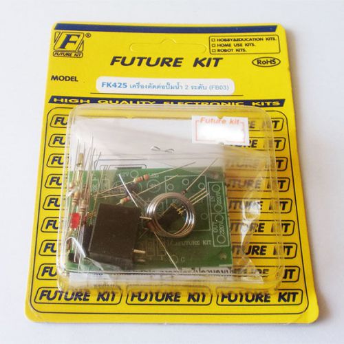
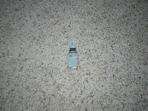
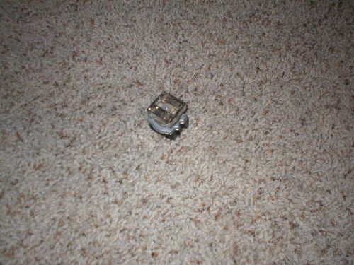
Brand | Future Kit |
| MPN | FK425 | ||
| Model | FK425 | ||
| Country/Region of Manufacture | Thailand | ||
| UPC | Does not apply |
Directions
Similar products from Automation Switches & Control Sensors
TELEMECANIQUE VW3A28100 KIT POTENTIOMETER START/STOP FACEPLATE
NEW IN BOX, IDEC TW-T246D LR48366 APW2246D-W CONTROL PANEL LIGHT
NEW, CUTLER-HAMMER E30EA COMPACT PUSH BUTTON SWITCH
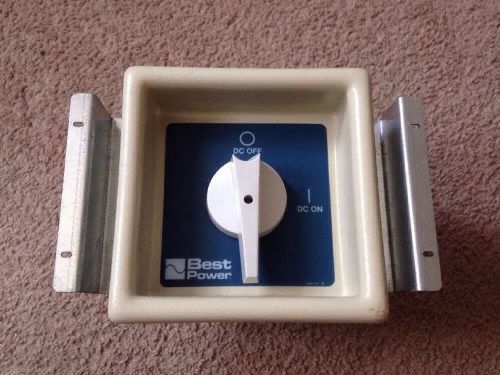
Entrelec VY 200 Best Power UPS Large Switch 600V 200A DC Power Huge Amps Master
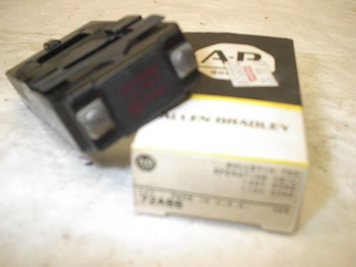
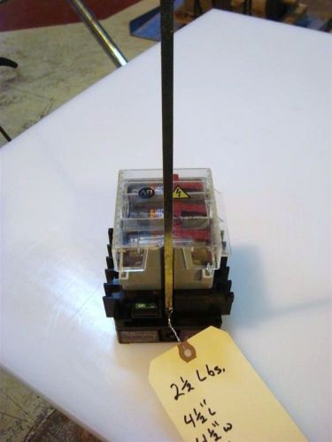
Allen Bradley operating coil 72A86, 120v, 60 Hz
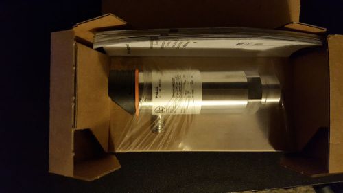
NEW EFECTOR PN4222 4222 EFEPN4222 PRESSURE SENSOR NIB
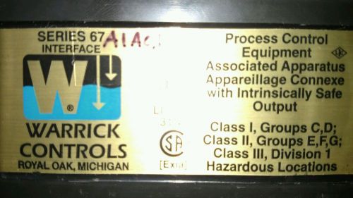
Warrick controls series 67 multifunction intrinsically safe Duplex controler
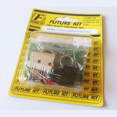
2x FK438 WATER LEVEL PUMP CONTROL 12VDC WITH ALARM BUZZER 240V,UN-ASSEMBLED KIT
Allen Bradley Molded Case Switch cat# 194R-NJ030P3 30A 600 VAC-250 VDC max
Challenger motor control CU13901 size 1, 3P voltage 200 230 460/575
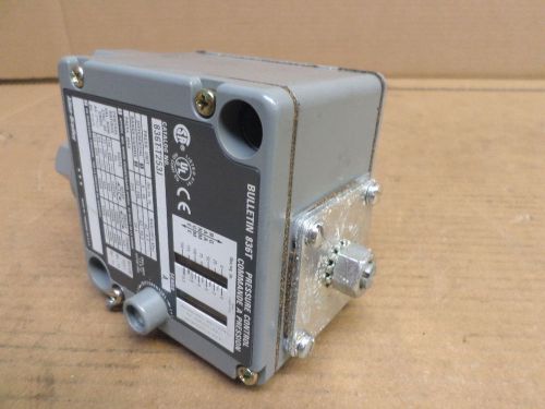
Allen-Bradey 836T-T253I Pressure Control
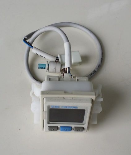
SMC / ISE03A-01-D / Pressure Switch, 12 to 24VDC, 2.4 to 20mA

Omron Genuine SHL-Q55 Limit Switch
No. 10X2141 Nkk Switches Lb15Wg Switch Pb Non-Illum Spdt 0.4vA 28V
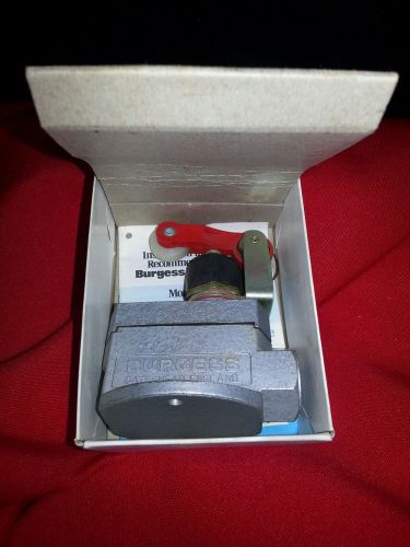
Burgess Micro Switch 15A-125-250-480 V.A.C.
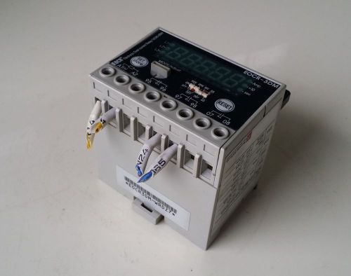
SAMWHA / EOCR-3DM-220 / Function Selector Switenes
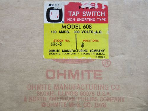
Ohmite 608-8 Power Tap Switch 100 Amp 8 Taps 300V NEW!!! Free Shipping
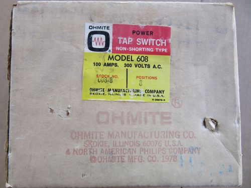
Ohmite 608-8 Power Tap Switch 100 Amp 8 Taps 300V NEW!!! in Sealed Box
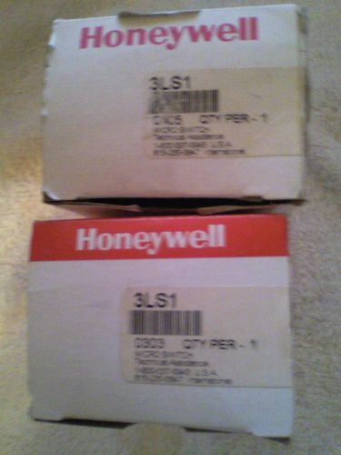
MODEL 3SL1 MICRO SWITCH OIL TIGHT LIMIT SWITCH HONEYWELL MH

Mercoid Control DA37-2RG9 Gauge 10-300 PSI 120/240V NEW!!! Free Shipping
People who viewed this item also vieved
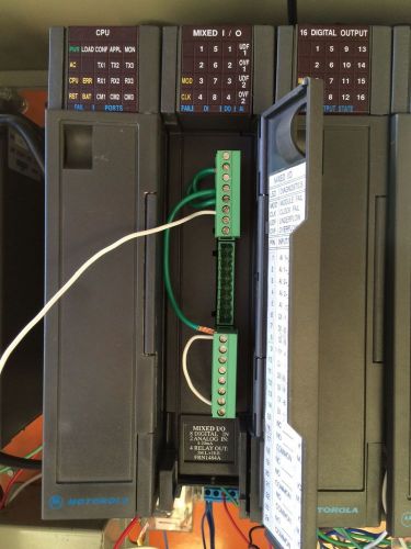
MOTOROLA FRN1484A MIXED I/O MODULE 8 DIGITAL IN 2 ANALOG IN 4 RELAY OUT USED
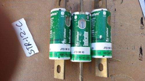
NNB .... LOT OF 3..... LITTELFUSE JTD 90 ID POWR-PRO CLASS J 600V-AC FUSE
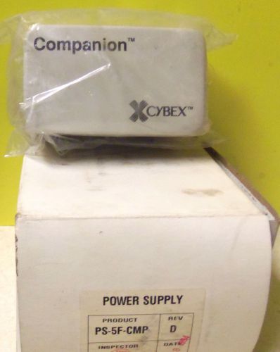
Cybex Companion~"CPW-280"~Receiver Rev-J1 Power Supply~BRAND NEW IN PACKAGE!
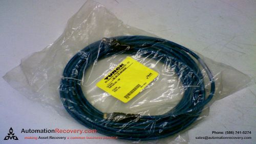
TURCK RJ45 RJ45 842-10M CORDSET ETHERNET 10 METER, NEW
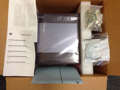
Allen Bradley Panelview 1000 2711-T10C20 Ser C Rev C FRN 4.20 Touchscreen
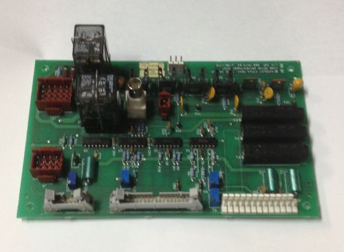
Nicolet NXR 1400 Motor Driver Board
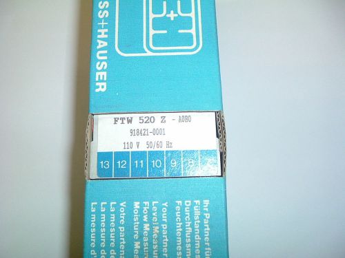
ENDRESS HAUSER FTW 520 Z A0BA 110VAC 50/60HZ PART 918421 0001 NEW BOXED
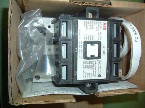
ABB EH 80 30 11 CONTACTOR 415-440 VAC 50 HZ NEW PACKAGED.
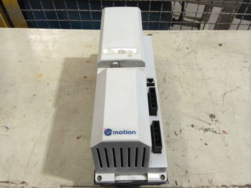
ABB DSQC 545A SERVO RECTIFIER 3HAB8101-19/07B
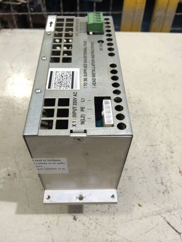
DSQC 608 CUSTOMER I/O POWER SUPPLY 3HAC12934-1
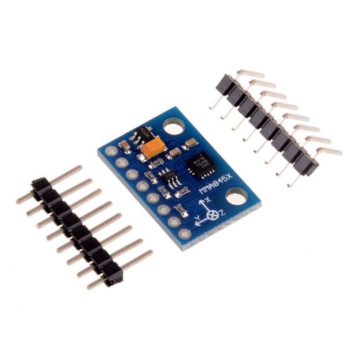
MMA8451 3 Axis Digital Accelerometer Tilt Module Triaxial Precision Acceleromete
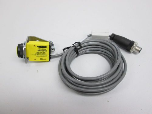
NEW BANNER SM312DSC MIN-BEAM SCANNER SHIELDED CASE SENSOR 10-30V-DC D259828
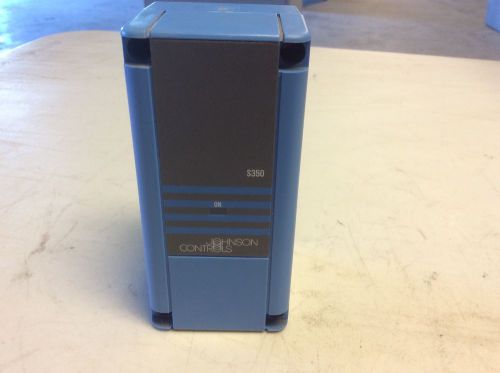
Johnson Controls S350AA-1C Temperature Controller Stage Module S350 S350AA1C
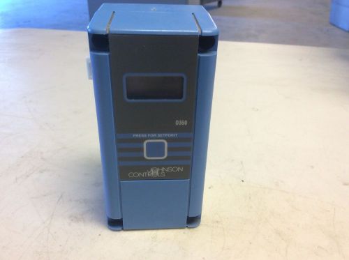
Johnson Controls D350AA-1C Temperature Controller Display Module D350 D350AA1C
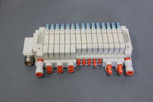
SMC 15 PORT AIR PNEUMATIC MANIFOLD & VLAVES Y5100-5U1 SY5400 SY5A00(S19-2-33J)
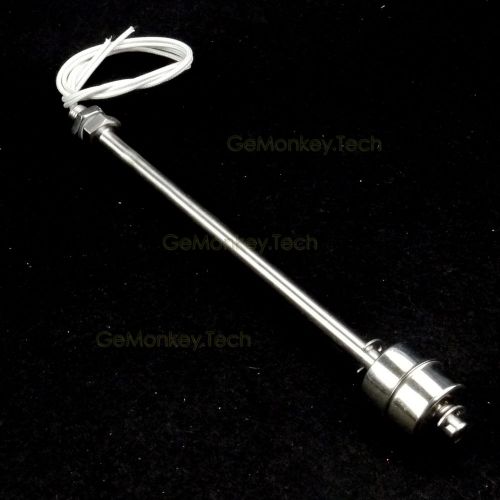
High-Temp Vertical Stainless Steel Liquid Water Horizontal Float Switch 8"
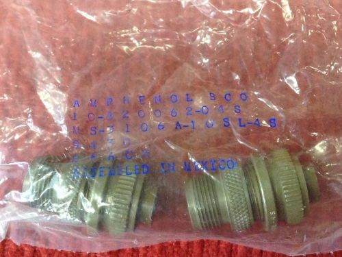
AMPHENOL - P/N: 10-820062-04S - Two (2), 2-Pin Female Connectors - NEW
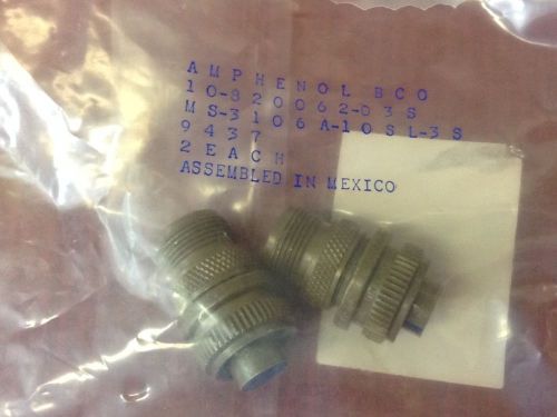
AMPHENOL - P/N: 10-820062-03S - Two (2), 3-hole Female Connectors - NEW
By clicking "Accept All Cookies", you agree to the storing of cookies on your device to enhance site navigation, analyze site usage, and assist in our marketing efforts.
Accept All Cookies