

US $63.82
| Condition: |
New: A brand-new, unused, unopened, undamaged item in its original packaging (where packaging is
applicable). Packaging should be the same as what is found in a retail store, unless the item is handmade or was packaged by the manufacturer in non-retail packaging, such as an unprinted box or plastic bag. See the seller's listing for full details.
...
|
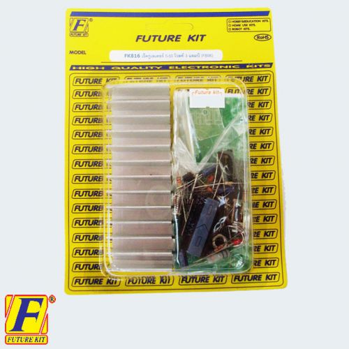
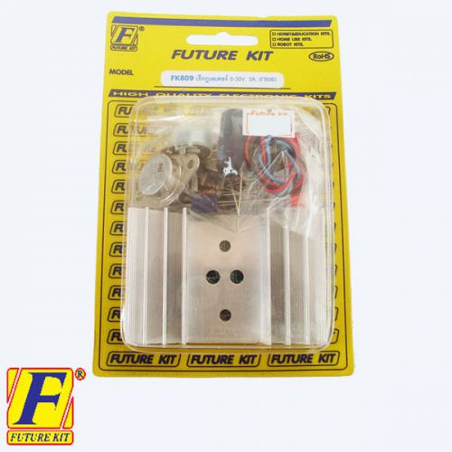
Brand | Future kit |
| MPN | 230715 | ||
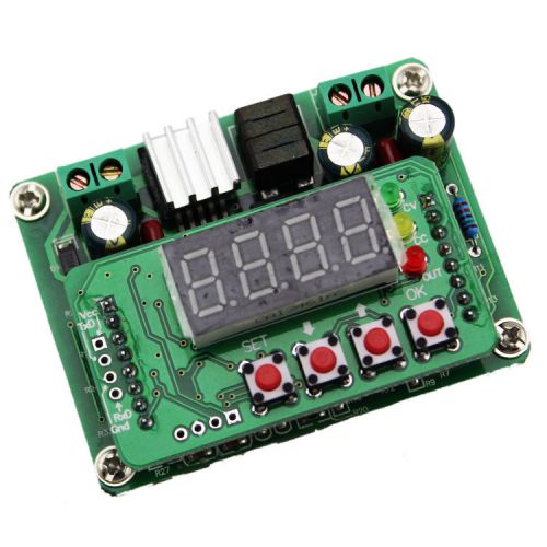
| Model | FK816 | ||
| Country/Region of Manufacture | Thailand | ||
| UPC | Does not apply |
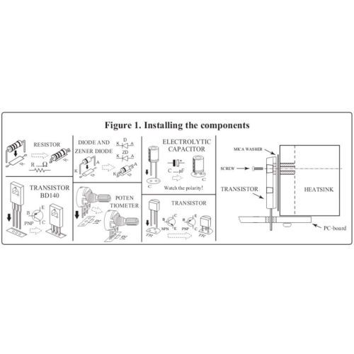
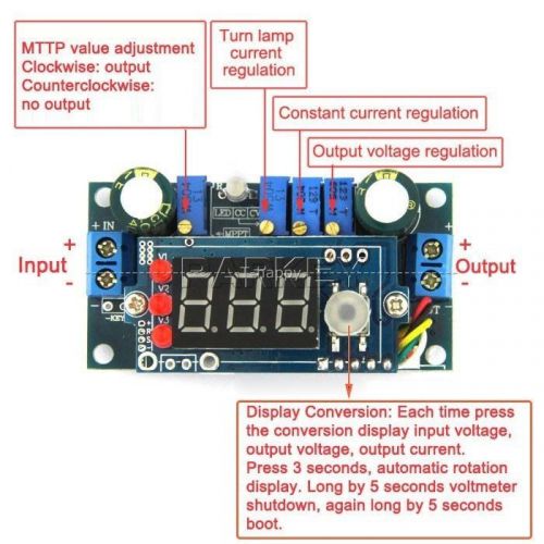
Directions
Similar products from Voltage Converters & Meters
(50) NSC LP2950ACZ-5.0 /NOPB 0.1A 5V 3TO-92 POSITIVE VOLTAGE REGULATOR ROHS
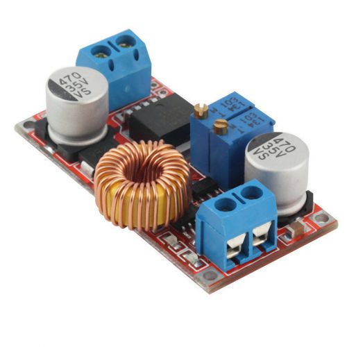
DC 10A CVCC Converter Buck 4.5-30V 24v to 0.8-28V 5v 9v 12v 19v Step Down Module
4.5-30V to 5V 9V 12V 24V DC Converter Constant Current Solar Battery Charger PWM
150W Boost 12v/24V DC Converter 8-32V to 9-46V Step-up Voltage Regulated Module
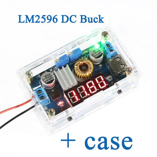
LM2596 DC Buck Regulator 5-36V to 24V 12V 5V 3.3V Step Down Module LED Voltmeter
Solar Panels MPPT Controller 5A DC buck Step-down Constant Voltage Current Modul
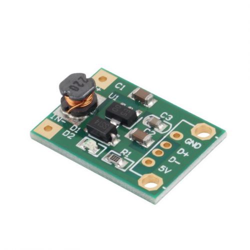
DC-DC Boost Converter Step Up Module 1-5V to 5V 500mA Power Module New SC2
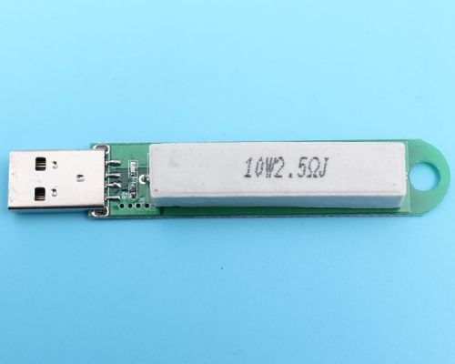
1pcs 2A USB Load Tester USB Current Tester Current Detection new

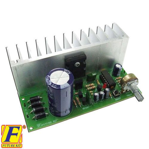
2x FA816 POWER SUPPLY REGULATOR VARIABLE MODULE,AC-DC,0-50V,3A,LM723,2SC5200,ELE
5A DC to DC CC CV Lithium Battery Step down Charging Board Led Power Converter H
Digital-controlled Constant Current LED Driver DC Step-Down Voltage Power Module
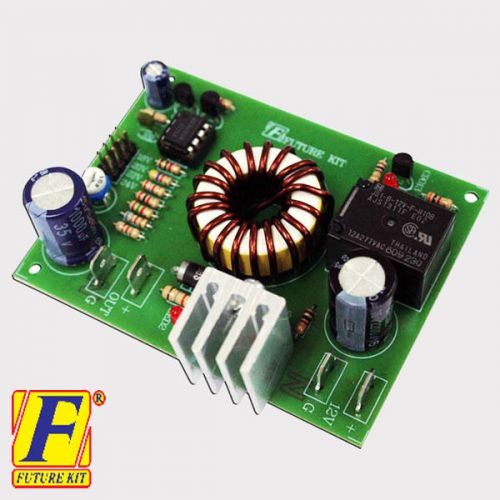
2x FA820 VOLTAGE CONVERTER BOOSTER,DC TO DC,CAR APPLICATION,CIRCUIT,ASSEMBLED KI
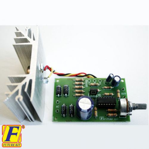
2x FA809 REGULATOR POWER SUPPLY VOLTAGE VARIABLE AC-DC MODULE 0-30V 3A,CIRCUIT B
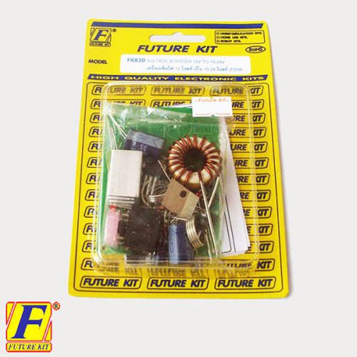
2x FK820 VOLTAGE CONVERTER BOOSTER,DC TO DC,CAR APPLICATION,CIRCUIT,UN-ASSEMBLED
2x FK809 REGULATOR POWER SUPPLY VOLTAGE VARIABLE AC-DC MODULE 0-30V 3A,CIRCUIT B
DC-DC Adjustable Step Down LM2596 Power Module 4.75-24V to 0.93-18V HC
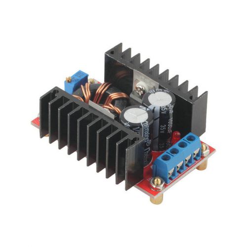
150W DC-DC Boost Converter 10-32V to 12-35V Step Up Charger Power Module HC
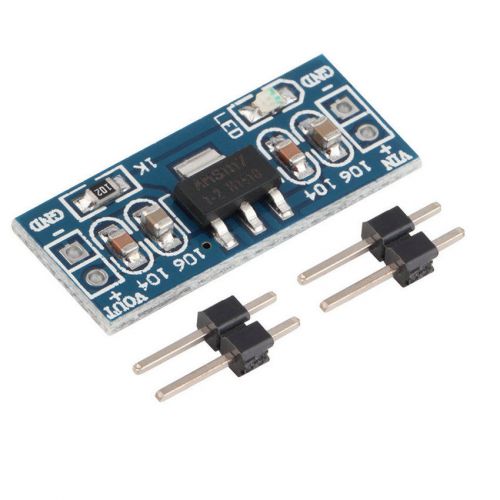
DC/DC AMS1117-1.2V Step-Down Voltage Regulator Adapter Convertor 2PSingle Row HC
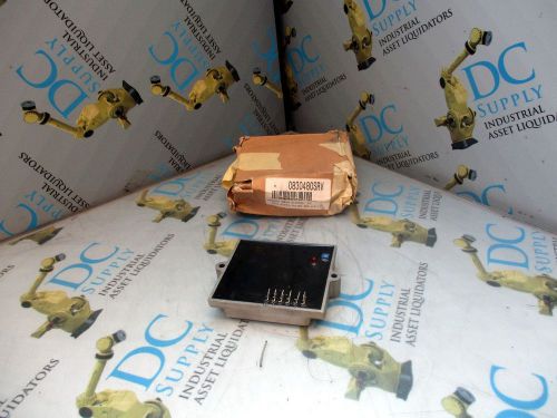
GENERAC 0830480SRV ASSY POTTED VOLTAGE REG W/O FIN
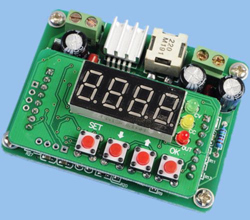
NEW LM2596S DC-DC Step Down LED Digital Display 6V-40V to 0-36V
People who viewed this item also vieved
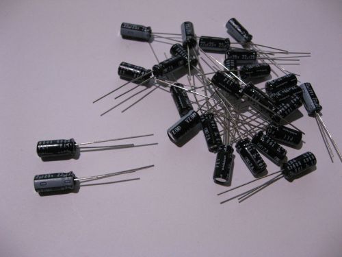
Qty 100 Electrolytic Capacitors 22 uF 25V 105C DEG Radial Leads - NOS
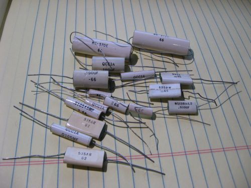
Lot of Northern Electric QCC1A & Similar Film Capacitors - NOS VINTAGE 1960s

NEW Anti Static Antistatic ESD Adjustable Wrist Strap Band Blue + 4FT Cord
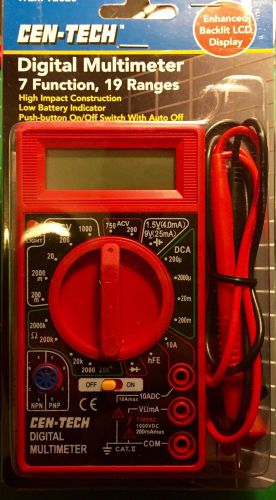
Cen_Tech 92020 Digital Multimeter
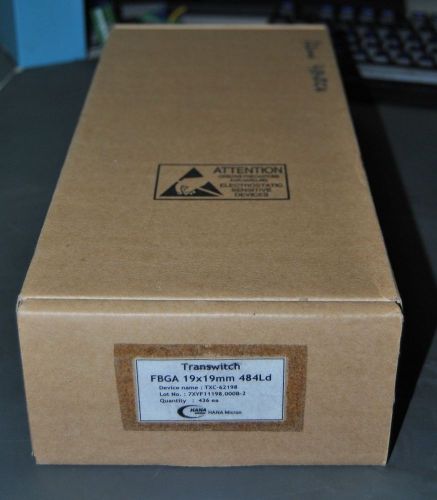
436 NEW TRANSWITCH FBGA TXC-62198 IC COMM CPU PROCESSOR (S5-4-51G)
![[50 pcs] E28F400B5B80 INTEL FLASH 80ns 4M 5V TSOP48](/_content/items/images/8/1985408/001.jpg)
[50 pcs] E28F400B5B80 INTEL FLASH 80ns 4M 5V TSOP48
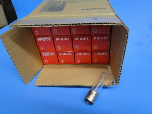
Phillips Tundsten Hallogen Lamp 15Q/CL/DC 120V BOX
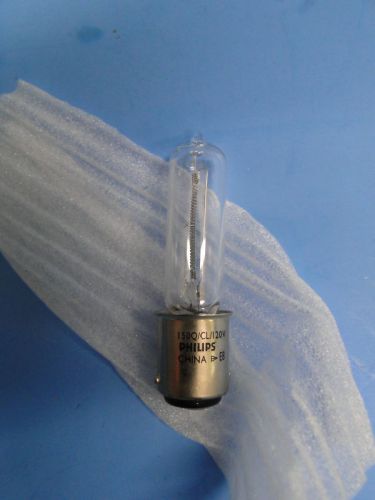
Phillips Tundsten Hallogen Lamp 15Q/CL/DC 120V
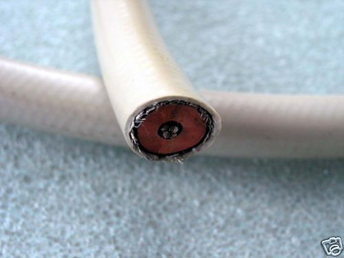
HIGH VOLTAGE X-Ray Cable 75KV tesla coil
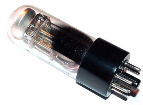
6E5S / 6E5G / 6G5G magic eye tubes. Lot of 2 pc. NOS!
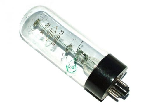
0.3B65-135 baretter tubes. Lot of 2 pc. NOS!
Make Basic Arduino Projects Feb 2014 PDF
Hitachi model GM 5- 4.5 inch viewfinder service manual
By clicking "Accept All Cookies", you agree to the storing of cookies on your device to enhance site navigation, analyze site usage, and assist in our marketing efforts.
Accept All Cookies