US $18.00
| Condition: |
New: A brand-new, unused, unopened, undamaged item in its original packaging (where packaging is
applicable). Packaging should be the same as what is found in a retail store, unless the item is handmade or was packaged by the manufacturer in non-retail packaging, such as an unprinted box or plastic bag. See the seller's listing for full details.
...
|
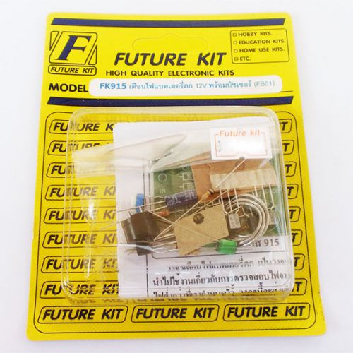
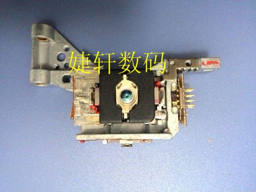
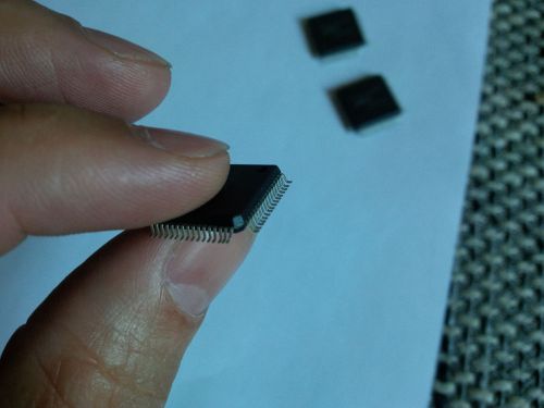
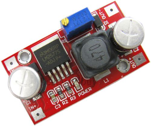
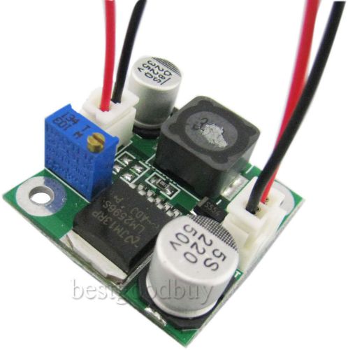
Brand | Future Kit |
| MPN | 120315 | ||
| Model | FK915 | ||
| Country/Region of Manufacture | Thailand | ||
| UPC | Does not apply |
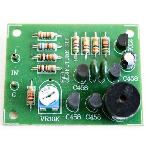
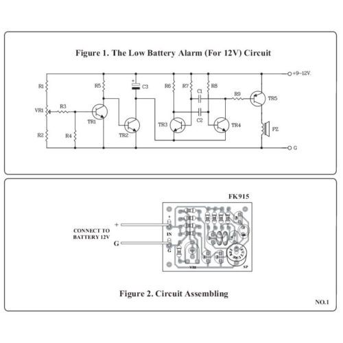
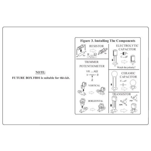
Directions
Similar products from Other Electronic Components & Spare Parts
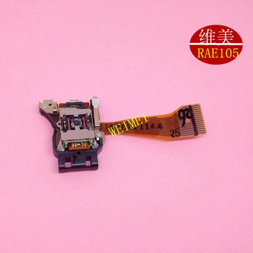
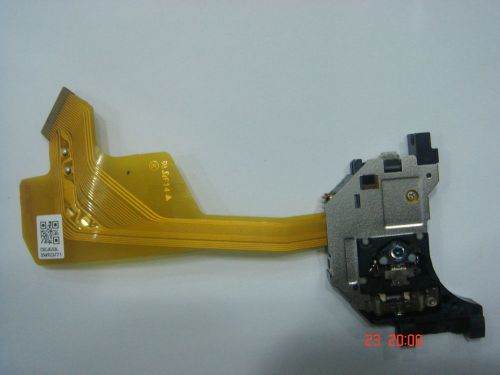
1PCS RAE-105 Original New Panasonic Laser Lens RAE105 Optical Pickup CD #A946 LW
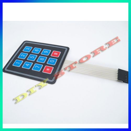
5pcs/lot 3 x 4 Matrix Membrane Switch Keypad Fit for SCM Peripheral Expansion
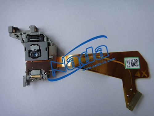
1PCS Car CD Lens Head Sharpe Optical Pickup Repair Part HPD-28AV #A947 LW
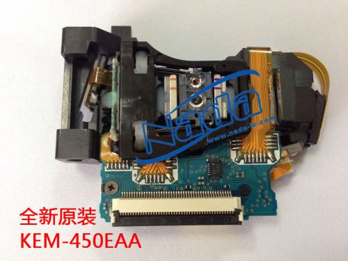
1PCS KEM-450EAA KES-450EAA Original Laser Lens for Sony #A948 LW
1PCS Optima-710 Original New JVC Laser Lens Optima710 Optical Pickup CD #A949 LW
SOH-DT2 Original New Samsung Laser Lens SOHDT2 Optical Pickup CD DVD #A950 LW
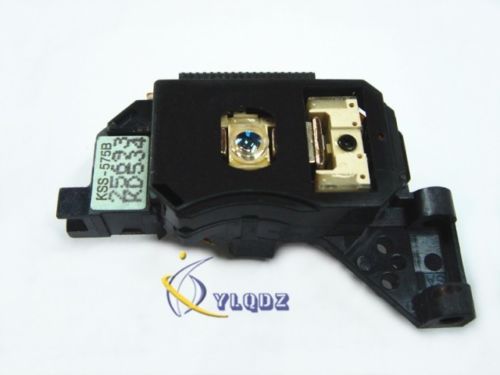
1PCS KSS575B Original New Sony Laser Lens Optical Pickup #A951 LW
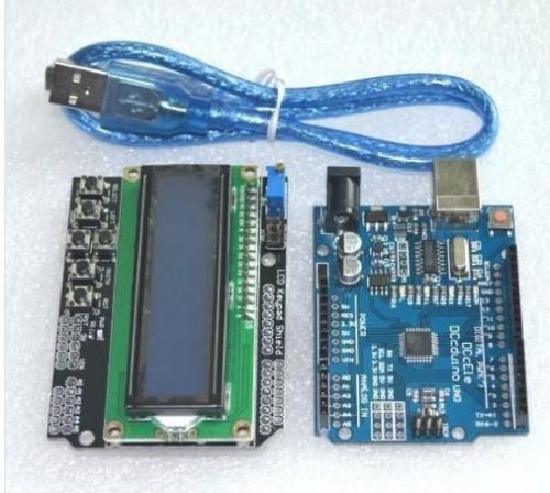
1602 LCD Keypad Shield expansion board for Arduino UNO R3 MEGA328P usb cable
1 x NJU6432BF JRC, QFP,DUPLEX LCD DRIVER IC, shipping from EU!
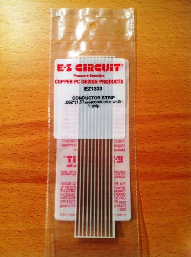
EZ Circuit Copper PC Conductor Strips for fast repair of Circuit Boards PCB RARE
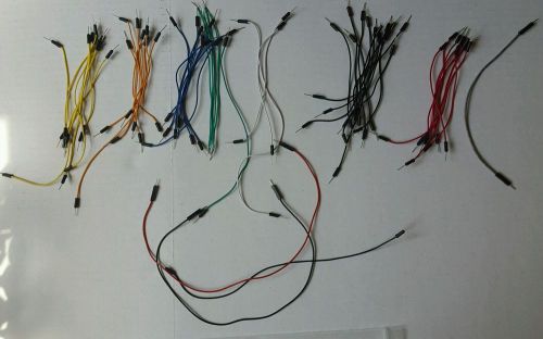
Assorted Electrical Connecting Wires (55 pieces) for breadboard
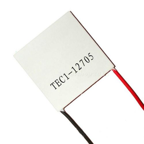
1 pc TEC1-12705 Heatsink Thermoelectric Cooler Cooling Peltier Plate Module SWTG
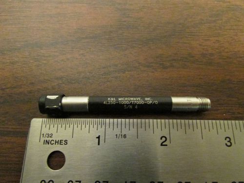
K&L Microwave 4L250-1000/T7000-0P-0 SMA Microwave Filter
1PCS NEW OPTICAL PICK-UP LASER LENS SF-HD80 FOR SANYO DVD #A905 LW
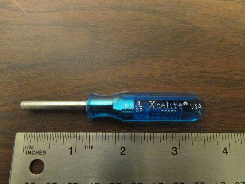
Xcelite 3/32 Nut Driver Hewlett-Packard Labeled Vintage
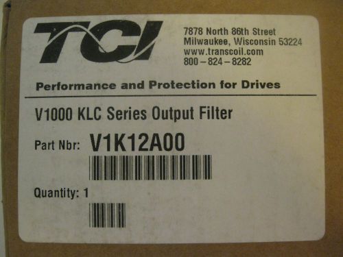
TCI V1000 KLC Series Output Filter, V1K12A00 (New in mfg sealed box)
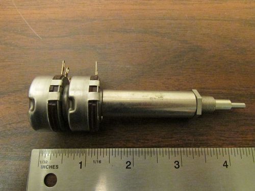
Ganged Dual Potentiometer 50k HP Tektronix Replacement Part NOS
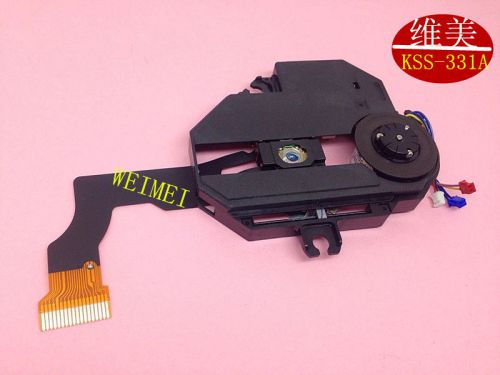
KSM-331AAN Original Sony Laser Lens Mechanism KSM331AAN Optical Pickup #A906 LW
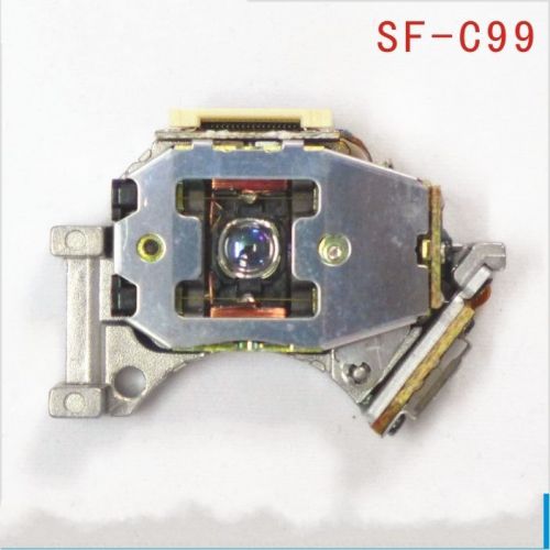
1PCS NEW OPTICAL PICK-UP LASER LENS SF-C99 FOR SANYO CAR CD #A907 LW
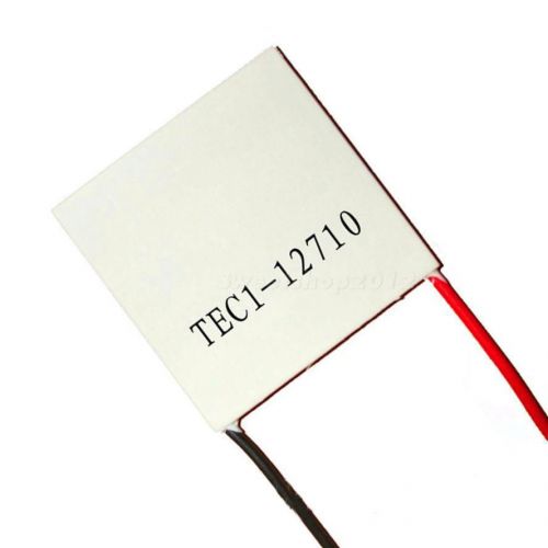
1Pcs TEC1-12710 Heatsink Thermoelectric Cooler Cooling Peltier Plate Module SWTG
People who viewed this item also vieved
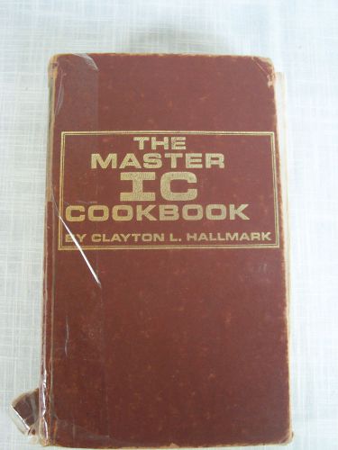
The Master IC Cookbook by Clayton L. Hallmark First Edition Ninth Printing 1980
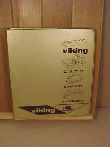
Lot of VIKING CATV System Products Catalogs 1965 Product Literature
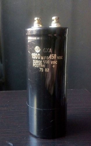
2 pc 1500uF 450V GXA capacitor TUBE AMP CAP HiFi Stereo 6l6 analog MFD
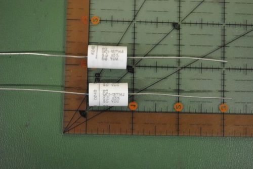
ELECTRONIC CONCEPTS POLYCARBONATE CAPACITOR 5uf 50v 5% MC1-13714J 5mfd AUDIO
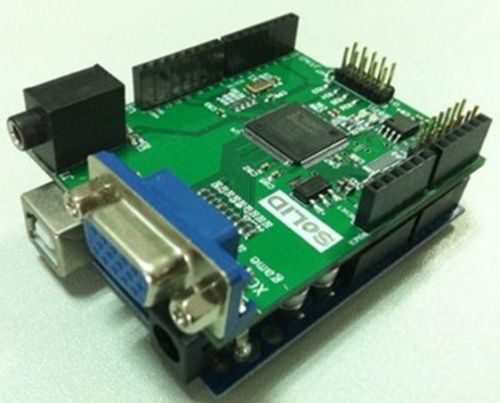
Gameduino VGA game development board / FPGA with serial Verilog source XC3S200
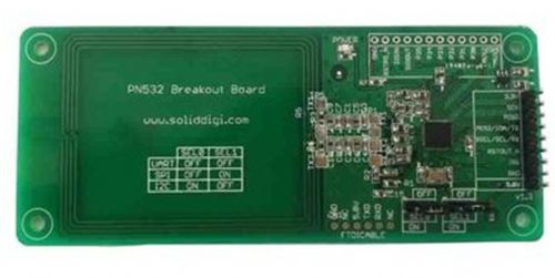
PN532 RFID/NFC Expansion Card v1.3 13.56MHz with white card
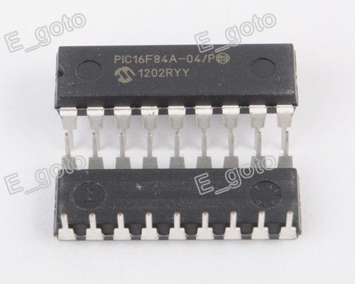
1PCS original DIP-18 PIC16F84A-04/P PIC16F84A 16F84A 18-pin DIP original
REAL ORIGIONAL Roland TB-303 Bassline Analog Synthesizer BRAIN IC CHIP NEW NOS
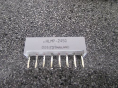
(20) Avago Optoelectronics Division HLMP-2450 miniature led lamps
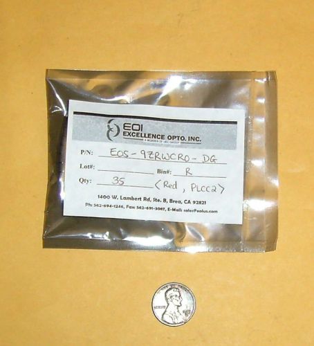
LOT OF 35 RED SMD PLCC2 LED #EOS-9ZRWCR0-DG by Exellence Opto.
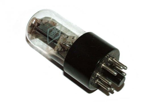
6N8S / 6SN7 / 1578 FOTON tubes. Lot of 4 pc. NOS!
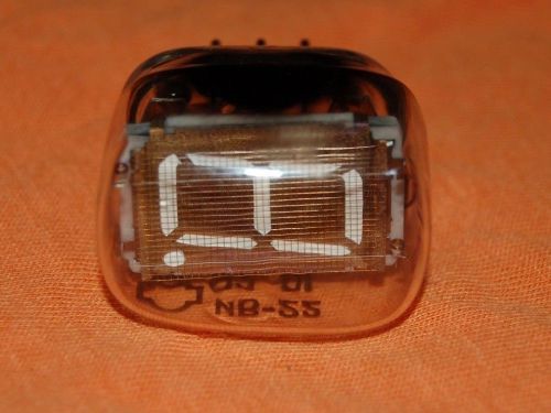
6 pcs. IV-22 IV22 Big 7 Segment VFD nixie tubes.NOS.
DC-DC 3.5-30V to 4.0-30V Adjustable Boost step-up power supply module Regulator
LM2596 4-40v to 1.5-35v DC to DC converter buck step down power supply Regulator
By clicking "Accept All Cookies", you agree to the storing of cookies on your device to enhance site navigation, analyze site usage, and assist in our marketing efforts.
Accept All Cookies