US $370
Directions
Similar products from Stepper Motor Driver Boards & Modules
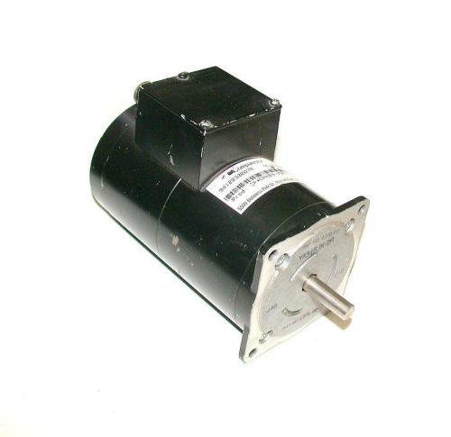
PARKER COMPUMOTOR CPH83-150 STEPPER MOTOR
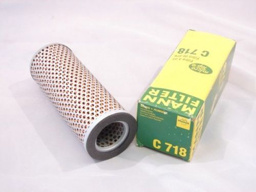
MANN FILTER C-718 MICRO TOP LUFTFILTER AIR FILTER ***NIB***
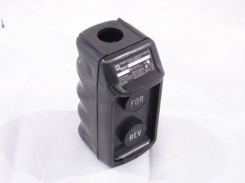
SQUARE D BW73B PENDANT STATION 600VAC 5A T-BW ***NNB***
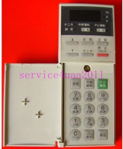
Mitsubishi inverter operation panel FR-PU03
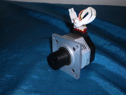
Applied Motion 4023-819 4023819 Stepping Motor
Vexta Oriental Motor PK245-01AA PK24501AA 2Phase 1.8deg. Stepping Motor
Pacific Scientific P21NSXC-LSS-NS-05 P21NSXCLSSNS05 1.8 deg. Step Motor
Pacific Scientific P2HNRXC-LSN-NS-03 P2HNRXCLSNNS03 1.8 deg. Step Motor
Oriental Motor CSD5814N 5 Phase Driver
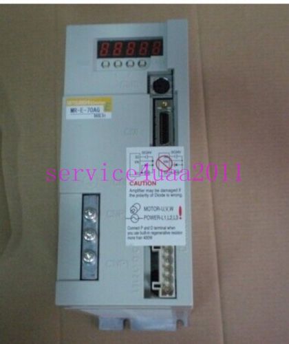
NEW Mitsubishi Servo Driver MR-E-70AG 2 month warranty
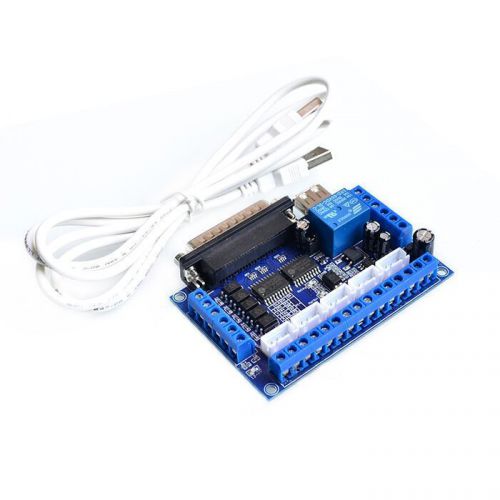
Upgraded 5 Axis CNC Breakout Board For Stepper Motor Driver Mach3 + USB Cable
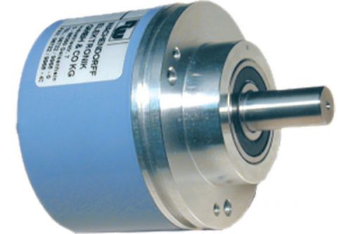
WACHENDORFF High resolution Encoder WDG 58B-400/500-AA-H24-S8-C18 discount
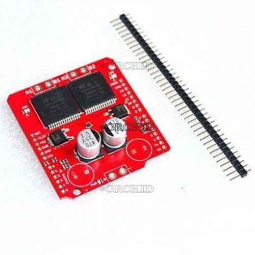
dual vnh2sp30 stepper motor driver module 30a monster moto shield replace l298n
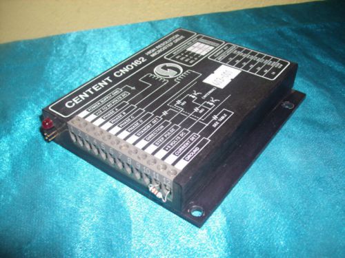
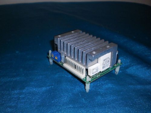
Centent CN0162 High Resolution Microstep Drive
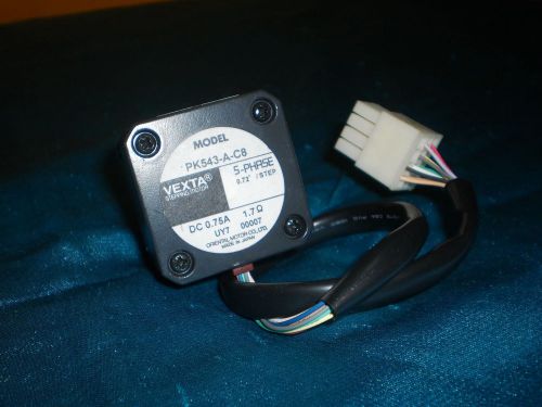
Oriental Motor PK543-A-C8 PK543AC8 5PH Stepping Motor
Shimpo MCDISPI Motion Controller 5 Phase Stepping Drive
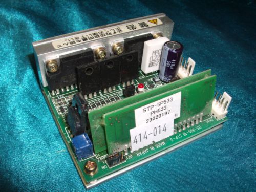
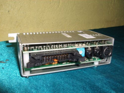
Vexta STP-5P533 PH533 Stepping Drive
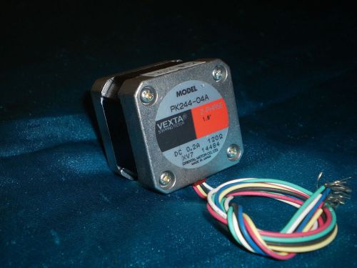
Oriental Motor PK244-04A PK24404A 2PH Stepping Motor
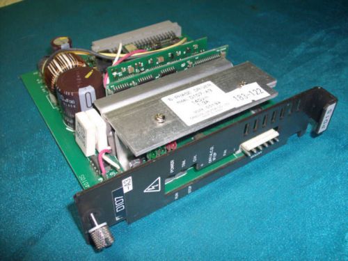
Oriental Motor D107-A3 D107A3 5 Phase Driver
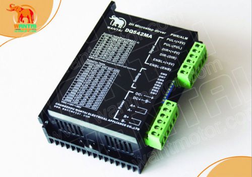
2-Phase Step motor driver 1PC DQ542MA 4.2A /18-50V to Nema23 CNC Digital
People who viewed this item also vieved
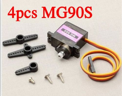
4pcs MG90S Metal Gear RC Micro Servo 9g for Align RC helicopter airplane boat
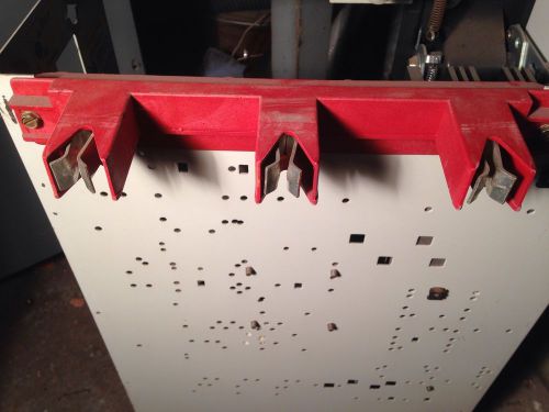
Westinghouse Five Star MCC Bucket Stab
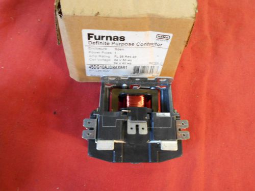
Furnas Definite Purpose Contactor 45DG10AJD8AX591 series C
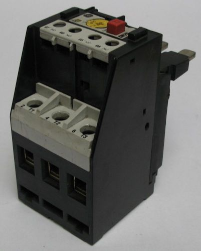
General Electric Type CR7G 3-Pole Overload Relay 64-75A CR7G5TJ USG
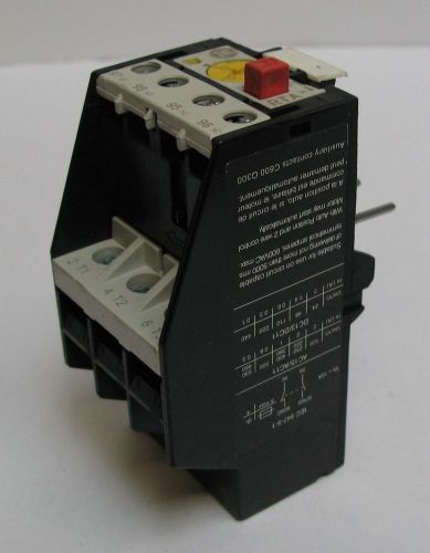
General Electric 3-Pole Class-10 Overload Relay 10-13A RTA1P USG
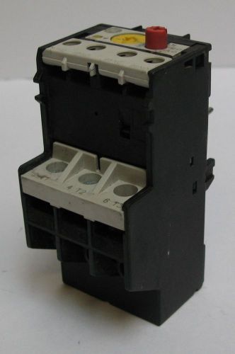
General Electric 3-Pole Class-10 Overload Relay 8-12A RT1N USG
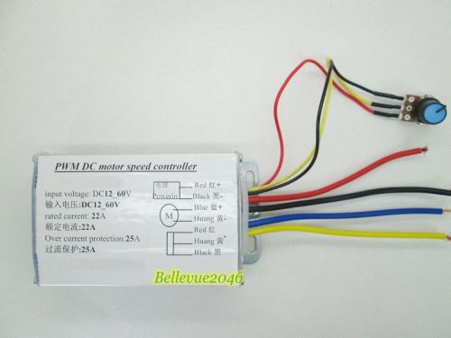
10-50V 60A DC Motor Speed Control RC 24V 48V 3000W MAX 0.01-3000W 15000HZ
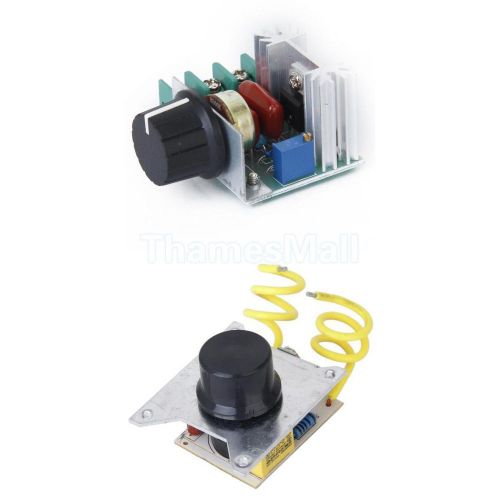
2pcs AC220V 2000W Voltage Regulator Dimming Dimmer Speed Temperature Controller
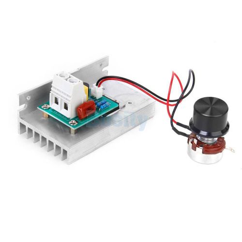
10000W AC220V SCR Voltage Regulator Motor Speed Controller Dimmer Thermostat
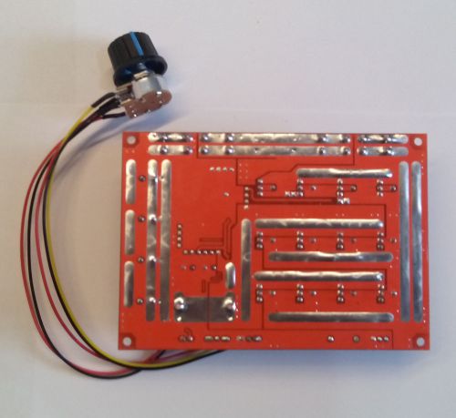
Max 1250W High Current DC Motor Speed Controller 12V 24V 36V 60V
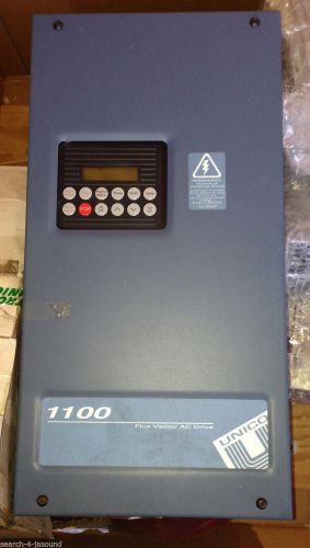
NEW Unico 1100 VFD Variable Frequency flux vector control AC Drive servo MOTOR
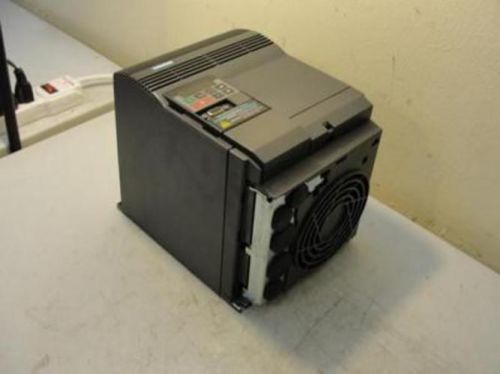
26289 New In box, Siemens 6SE3221-3DC40 Motor Controller 5500W 380/500V 17.1A
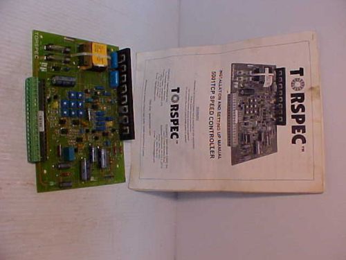
Torspec 5001 TCP Adjustable Speed Drive
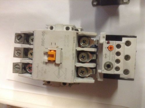
Benshaw Contactor RSC-85 NEMA Size 3 With SPOT-85 RELAY AND 240V COIL
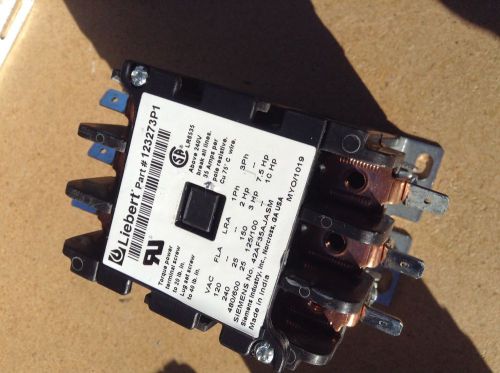
Emerson Liebert 123273P1 240/480/600 Volts 30 Amp Contactor FURNAS 75D70641J
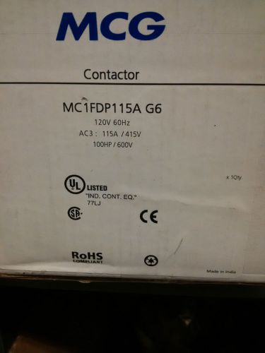
Brand New Sealed MCG MC1FDP115A G6 AC3 115A 415V 100HP 600V Contactor
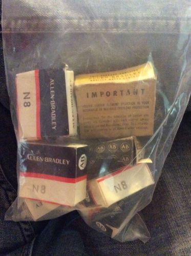
LOT OF 10 ALLEN BRADLEY N8 Overload Heater Element
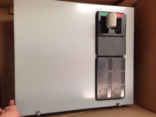
Cutler Hammer 400 amp 600 volt feeder bucket
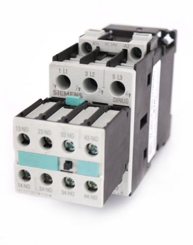
Siemens Sirius 3RT1024-1B..0 Coil Contactor Starter 3-Pole +3RH1921-1FA40 Block
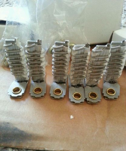
GE thermal overload heating element cr 123268a total of #6 in this set
By clicking "Accept All Cookies", you agree to the storing of cookies on your device to enhance site navigation, analyze site usage, and assist in our marketing efforts.
Accept All Cookies