US $49.99
| Condition: |
New: A brand-new, unused, unopened, undamaged item in its original packaging (where packaging is
applicable). Packaging should be the same as what is found in a retail store, unless the item is handmade or was packaged by the manufacturer in non-retail packaging, such as an unprinted box or plastic bag. See the seller's listing for full details.
...
|
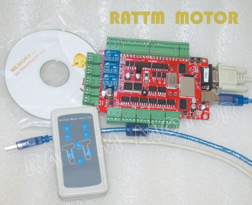
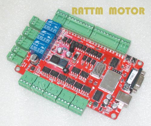
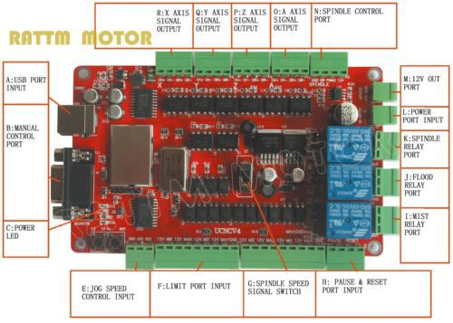
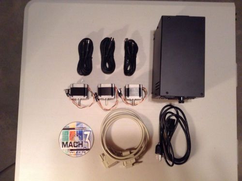
Brand | RATTM MOTOR |
| Name | 4 axis USBCNC controller | ||
| Model | USBCNCV4.0 | ||
| Port | USB port | ||
| MPN | http://hgauto.en.alibaba.com/ | ||
| Color | Red | ||
| Country/Region of Manufacture | China | ||
| Weight | 0.45kgs |
Directions
Similar products from Professional Router Machines
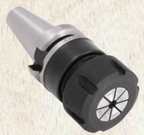
Techniks BT 40 ER 32-100mm 25K RPM @ G2.5 Balanced CNC Collet Chuck-.0001" TIR
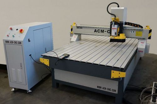
Brand New CNC router 4'x8' - ACM Brand
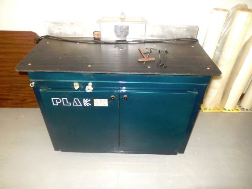
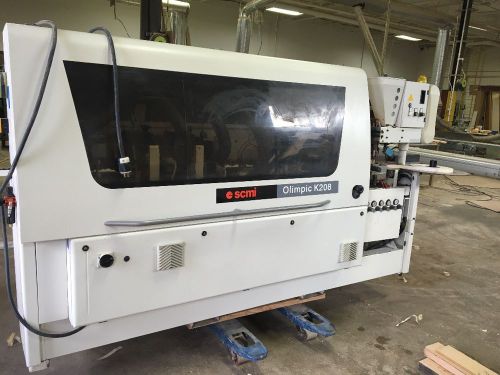
PLAK 4590 PROFESSIONAL ROUTER*VERY GOOD CONDITION
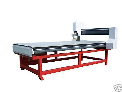
4'X8' CNC Table Router System!
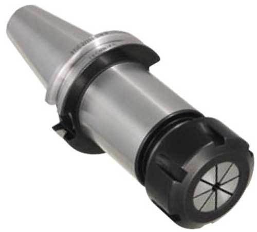
Techniks CAT 50 ER 32-4" 25K CoolFlex (DIN B and Coolant-Thru) CNC Collet Chuck
3 Axis Complete CNC Set- Software-Router-Turning Center-Milling Machine-
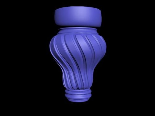
3D model of STL excellent kachestva.cnc
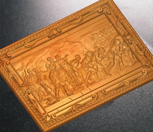
1313 CNC 3d Relief Model STL for Router Engraver Mill Woodworking 3D printer
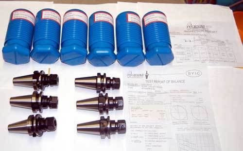
6 Pcs. Techniks BT 30 ER 16x 60mm 25K RPM @ G2.5 Balanced CNC Collet Chucks
CNC 3D Router Models in STL Format / Trim and Panel / CNC Machines / Engrave NR!
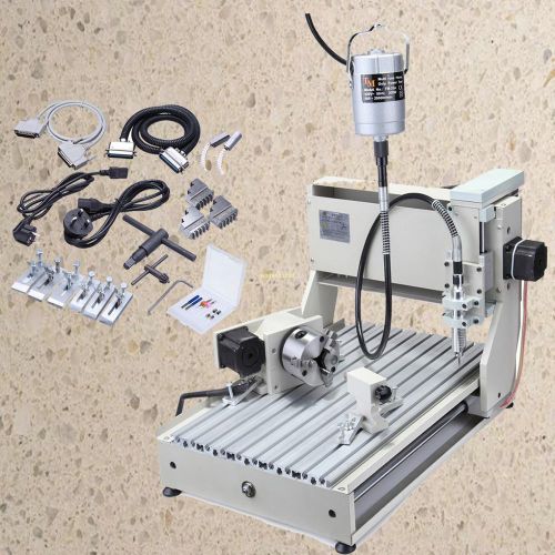
3040C 4 Axis CNC Router Engraver Handicraft Anaglyph Badges Engraving Machine

3 d model stl artcam cnc router
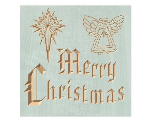
Merry Christmas Graphic, G-code Mach 3 and Generic versions
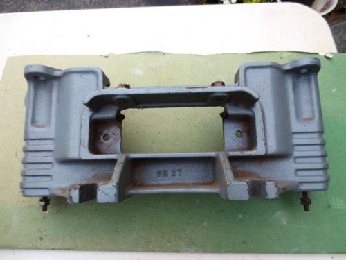
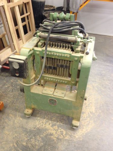
Delta Rockwell Homecraft router wood shaper Main casting/ rear legs
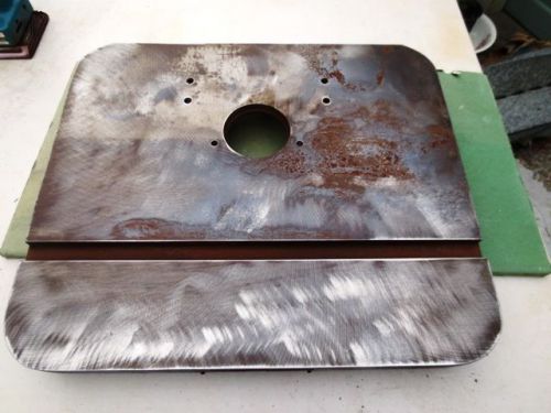
Delta Rockwell Homecraft Wood Shaper Table top Casting SR101
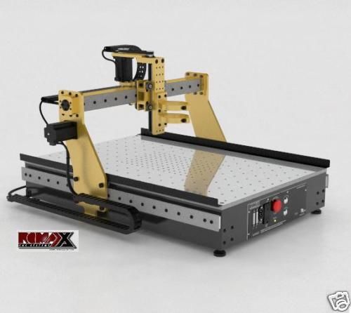
Romaxx CNC 3 axis Router Machine table 24X36 ballscrew
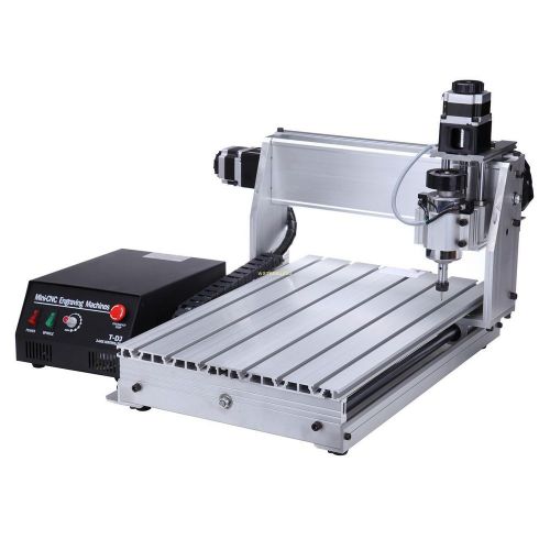
3 Axis CNC 3040T-DJ Router Engraver Engraving Machine + Clamp Tools
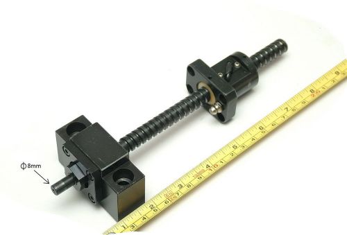
NSK C3 ground ballscrew 12-5mm L215mm Travel 115mm BALL SCREW
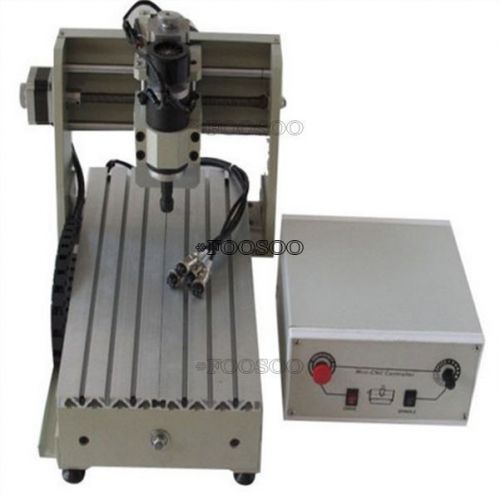
ROUTER CNC ENGRAVER DESKTOP 3020T DRILLING/MILLING MACHINE ENGRAVING
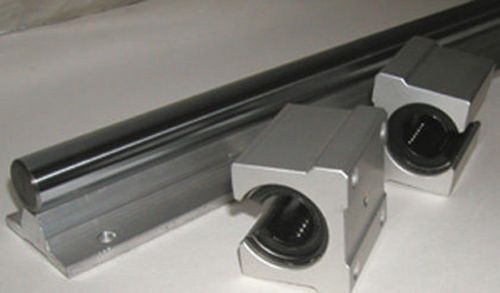
CNC Supported Shaft 20mm 55" an 2 Bearing Special $99
People who viewed this item also vieved
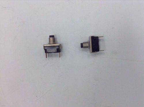
Delta 1313172 Brake Switch For 34-080 Mitre Saw
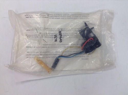
Porter Cable - Delta 889640 Switch (863 And 873 Drills)
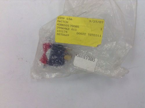
Delta 438010170085 Switch (33-892 Radial Arm Saw)
Walker Turner Craftsman Bench Saw Parts B735/745 (?)
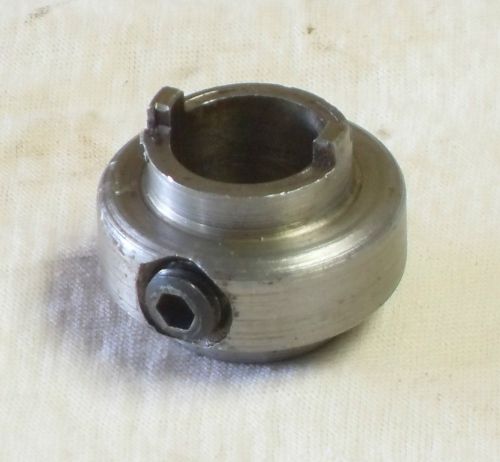
DELTA ROCKWELL Drill press Upper bearing Drive Collar #DP-250
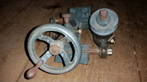
Clausing Drill Press Model 2274 - PARTS AVAILABLE
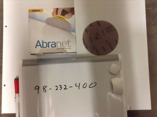
Mirka 9A-232-400 Abranet 5" 400gr Mesh Grip Dust-free Sanding Disc 50pk
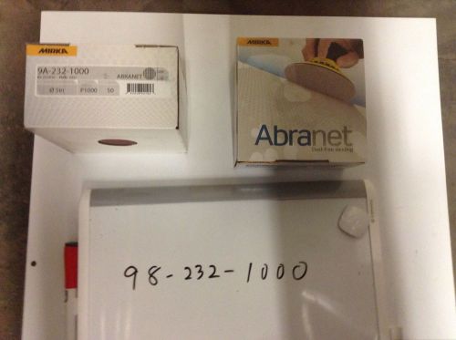
Mirka 9A-232-1000 Abranet 5" Mesh Grip (H&L) 1000gr Sanding Disc 50pk
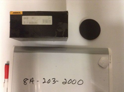
Mirka Abralon 8A-203-2000 3" Foam Sponge Back Grip Wet/Dry Discs/20bx
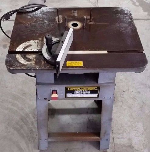
Central Machinery Industrial Router Table
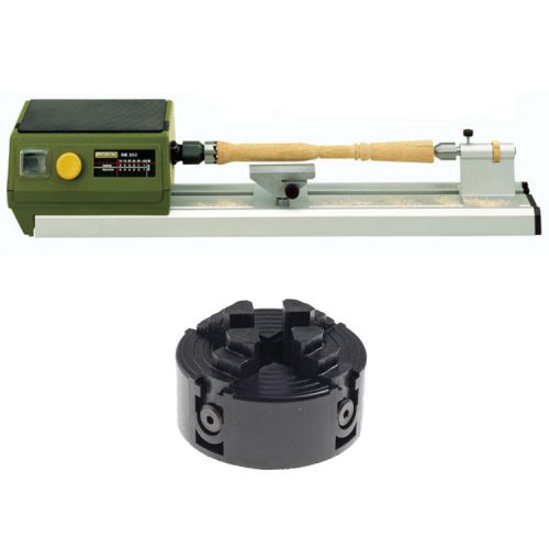
Proxxon 37020 DB 250 MICRO Lathe, 27024 4-Jaw Chuck for Proxxon DB 250
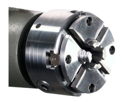
Nova Js20n Mini 20Mm Chuck Accessory Jaw Set Special Nova Dovetail Profile, Des
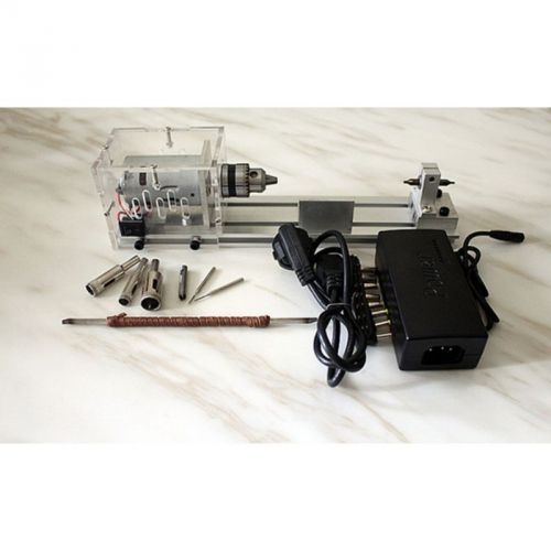
Mini Lathe Beads Machine Woodworking DIY Lathe Standard Set with Power DC 24V
By clicking "Accept All Cookies", you agree to the storing of cookies on your device to enhance site navigation, analyze site usage, and assist in our marketing efforts.
Accept All Cookies