

US $630
| Condition: |
New: A brand-new, unused, unopened, undamaged item in its original packaging (where packaging is
applicable). Packaging should be the same as what is found in a retail store, unless the item is handmade or was packaged by the manufacturer in non-retail packaging, such as an unprinted box or plastic bag. See the seller's listing for full details.
...
|
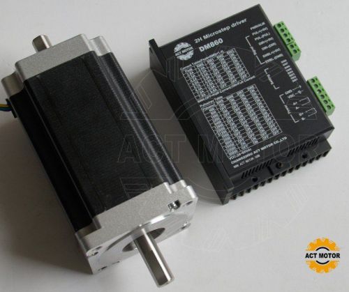
Brand | ACT |
| Country/Region of Manufacture | United States | ||
| Model | 34HS5435 & DM860 |
Directions
Similar products from Stepper Motor Driver Boards & Modules
New 4 Axis TB6560 CNC Stepper Motor Driver Controller Board Kit,57 two-phase,3A
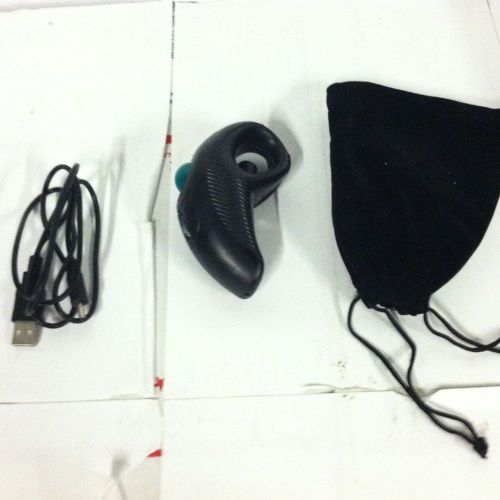
DBPOWER UPNP Wireless Finger Handheld 2.4GHz Mouse with Trackball
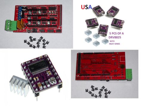
RAMPS1.4 3D PRINTER BOARD & 5PCS DRV8825 DRIVERS WITH HEAT-SINKS USA SHIP !
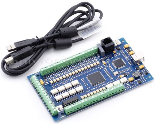
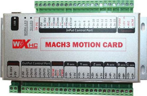
CNC USB 3 Axis 1Mhz Mach3 Motion Controller Card Interface Breakout Board E-CUT
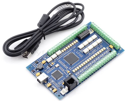
CNC 3 Axis 1Mhz Mach3 USB Motion Controller Card Interface Breakout Board E-CUT
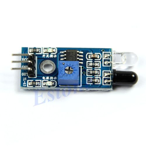
Infrared Obstacle Avoidance Smart Car Module Reflection Photoelectric Sensor Hot
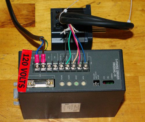
Oriental Motor Co. 5-phase Driver Stepper Motor
Third Generation 6 Axis USB Mach3 CNC Motion Control Card Breakout Board
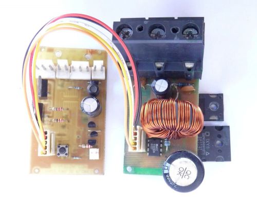
PWM DC Converter, 12V-35V 5A 10A DC Motor Speed Adjuster Controller Driver
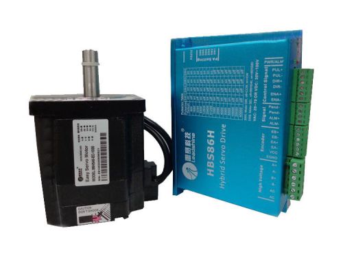
Leadshine HBS86H 2-Phase Hybird servo Drive+86HS40-EC Stepper motor 4N.m NEMA 34
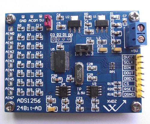
ADS1256 24Bit ADC AD module Precision ADC data acquisition card collection
Versatile USB Port MACH3 motion control card Engraving machine control panel
Mini Upgrade XHC MK3 CNC Mach3 USB 4 Axis Motion Control Card Breakout Board
3Axis CNC controller kit Nema23 Stepper Motor 308oz-in&3 Axis Board&Power supply
Dual H Bridge DC Stepper Motor Drive Controller Board Module Arduino L298N WW
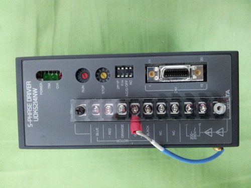
VEXTA UDK5214NW2 5-PHASE DRIVER
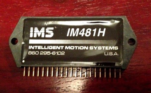
IM481H MICROSTEPPING DRIVER BY IMS
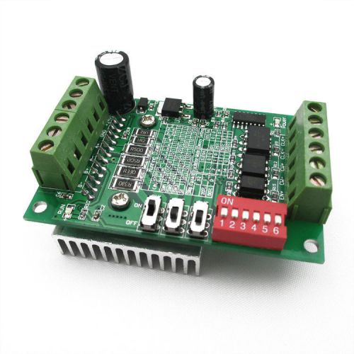
CNC Router Single Axis TB6560 Stepper Motor Drivers Controller 3A for Arduino
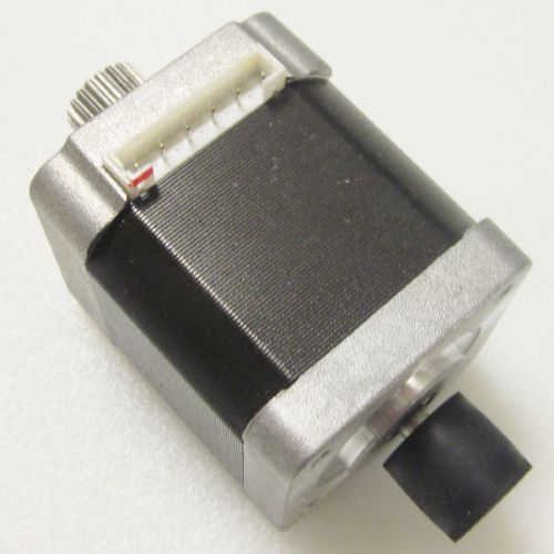
Japan Servo KH42KM2R042 1.8 Stepper Motor 6 Wire Lead
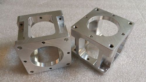
Nema 23 Stepper Motor Mount (with 4 open sides)
People who viewed this item also vieved
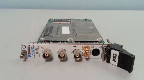
NATIONAL INSTRUMENTS NI PXI-5124 200 MS/s, 12-Bit Oscilloscope/Digitizer NEW
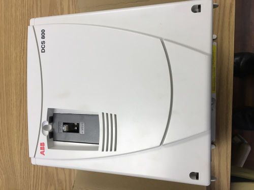
ABB DIGITAL DC DRIVE DCS800-S02-0025-05-0 (3-525V) NEW
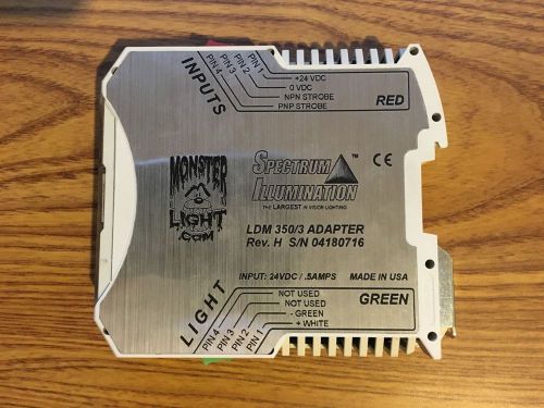
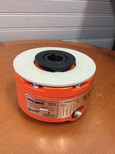
SPECTRUM ILLUMINATION LDM 350/3 REVISION H CONTROLLER ADAPTER (USED)
SIEMENS SERVO MOTOR 1FT5066-1AF71-3EBO
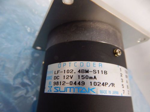
SUMTAK OPTCODER LF-102. 4BM-S11B 9812-0449 1024P/R
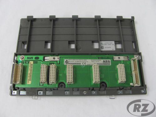
DTA200/AS-HDTA-200 MODICON ELECTRONIC CIRCUIT BOARD NEW
Westinghouse Type A Heater FH88 S.N. 179C319G18 3-Pack
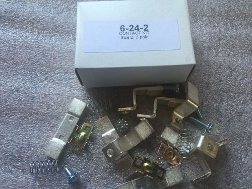
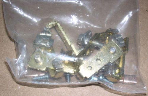
New 6-24-2 Contact Kit for Eaton/Cutler-Hammer Size 2 3 Pole Contactor
SIEMENS, MAIN CONTACT KIT FOR CONTACTOR, 3TY6440-0A
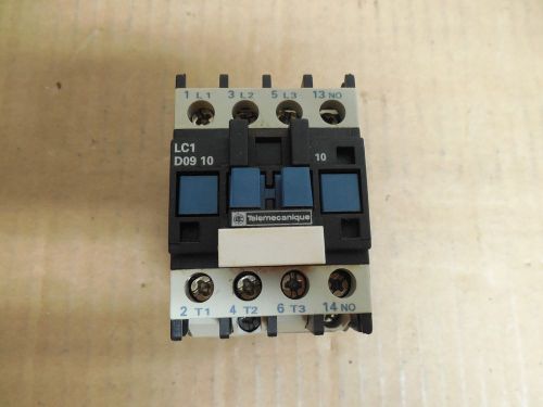
TELEMECANIQUE CONTACTOR LC1 D09 10 110V COIL 25A A AMP 600Vac LC1D0910
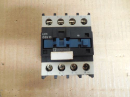
TELEMECANIQUE CONTACTOR LC1 D25 10 40A A AMP 110V COIL 600Vac LC1D2510
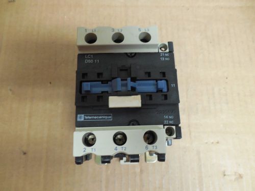
TELEMECANIQUE CONTACTOR LC1 D50 11 110V COIL 80A A AMP 600Vac LC1D5011
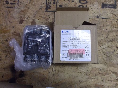
Eaton C25DND330T 30 Amp Definite Purpose Contactor FREE SHIPPING
New 9v-36V15A PWM converter DC Motor Speed Control switch f/12v24v pump car lamp
DART CONTROLS 5HA33 L11-00493 DC Motor Speed Control 120 VAC 130LC100
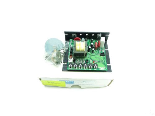
NEW MINARIK MM23012D-0163 115/230V-AC 90/180V-DC 1.3A 1/4HP MOTOR DRIVE D509779
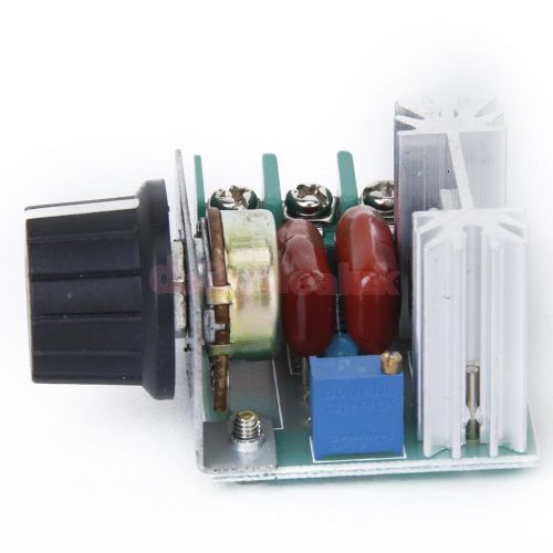
High-power 2000W SCR Voltage Regulator Dimmer Speed Temperature Controller
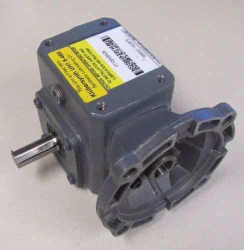
BOSTON GEAR F7105KB4G6 5:1 RATIO WORM GEAR SPEED REDUCER GEARBOX
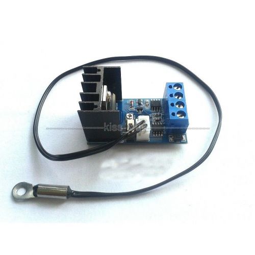
DC 12V 1A Automatic PC CPU Fan Temperature Control Speed Controller + Sensor
BOSTON GEAR F7105SVB4G6 5:1 RATIO WORM GEAR SPEED REDUCER GEARBOX
By clicking "Accept All Cookies", you agree to the storing of cookies on your device to enhance site navigation, analyze site usage, and assist in our marketing efforts.
Accept All Cookies