US $13.00
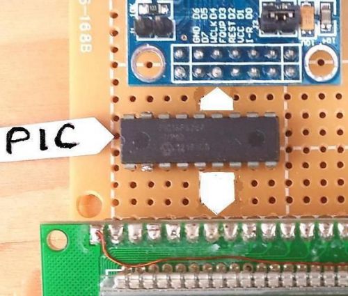
| “NEW-PRE-PROGRAM MICRO” |
| Brand | KAM CODE |
| MPN | KAMCODE |
| Model | VERSION 2V3x |
Directions
Similar products from Signal Generation Equipment
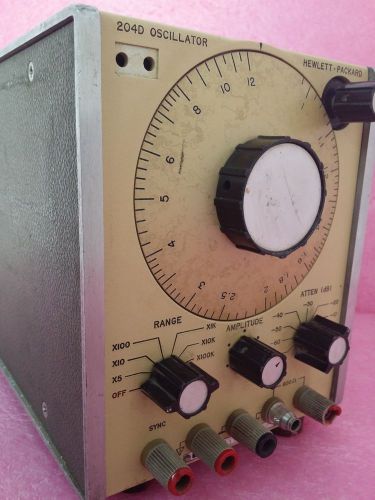
HP Hewlett Packard 204D Oscillator Vintage
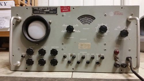
Antique Military Compudyne Signal Generator TS-452 D/U
HP HEWLETT PACKARD 8614A SIGNAL GENERATOR 0.8-2.4GHz (E)

HP HEWLETT PACKARD 8614A SIGNAL GENERATOR 0.8-2.4GHz (A)
HP HEWLETT PACKARD 8614A SIGNAL GENERATOR 0.8-2.4GHz (B)
HP HEWLETT PACKARD 8614A SIGNAL GENERATOR 0.8-2.4GHz (C)
MILITARY SIGNAL CORP SIGNAL GENERATOR
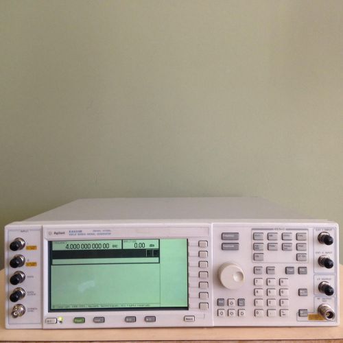
HP Agilent E4433B ESG-D 250KHz - 4GHz Signal Generator W/ OPT UN8 UN9 UND
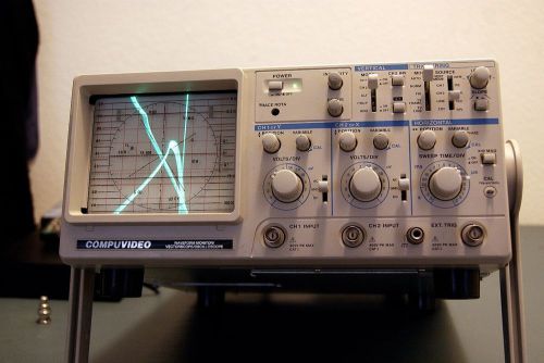
Compuvideo SVR-1100A Waveform Monitor/Vectorscope/ Oscilloscope, Used W/Pwr Cord
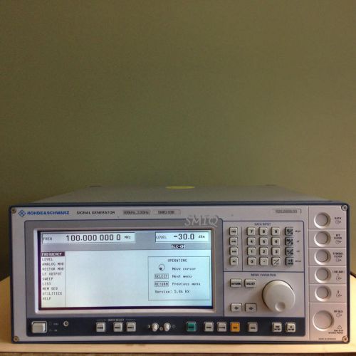
Rohde Schwarz SMIQ03B RF Signal Generator 3.3 GHz + opt. B5, B19
GENRAD SIGNAL GENERATOR 1310-A OSCILLATOR FREQUENCY OUTPUT RADIO MILITARY USED
GENRAD SIGNAL GENERATOR 1310-B OSCILLATOR GENERAL RADIO FREQUENCY MILITARY USED
GENRAD SIGNAL GENERATOR 1310-B OSCILLATOR RADIO FREQUENCY OUTPUT MILITARY USED
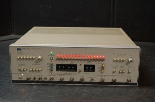
HP Agilent 8018A Serial Data Generator
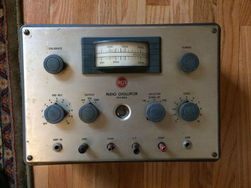
Vintage RCA Audio Oscillator WA-54A Signal Generator
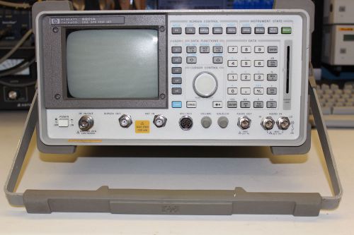
HP 8921A 8920A SERVICE MONITOR TEST SET SPECTRUM ANALYZER TRACKING GENERATOR
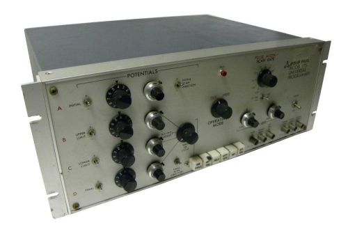
EG&G 175 UNIVERSAL PROGRAMMER SIGNAL GENERATOR
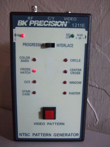
BK PRECISION 1211E Handheld NTSC PATTERN GENERATOR

1993 Cummins Onan Genset Generator 150 KW Model # 1250DGEA Diesel Stationary
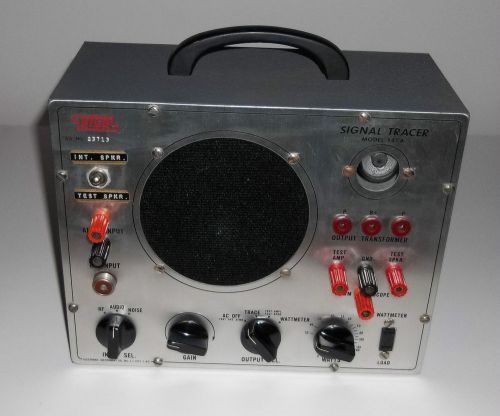
EICO 147A Signal Tracer Tested & Works Great
People who viewed this item also vieved
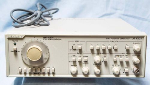
Leader Electronics Freqency 2mhz Function Generator
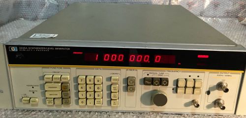
HP 3335A SYNTHESIZER/LEVEL GENERATOR
ENERGY CONCEPTS DIGITAL DISPLAY MODULE 21700
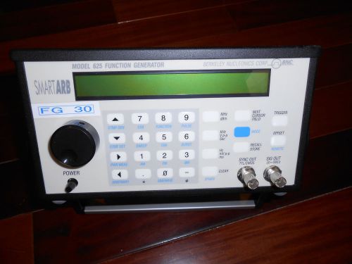
BERKELEY NUCLEONICS 625/625A FUNCTION GENERATOR
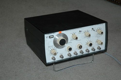
Wavetek 145 pulse/function generator, Fully tested, Works Great
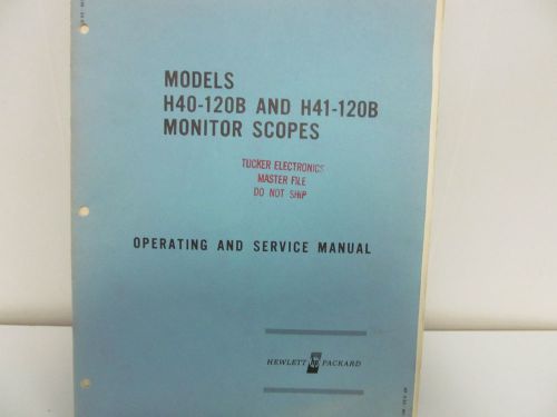
HP H40-120B/H41-120B Monitor Scopes Operating & Service Manual-w/schematics
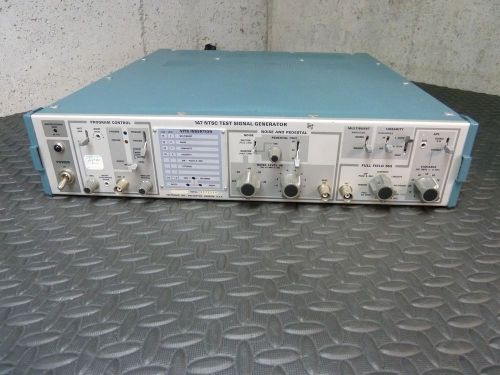
FREE SHIPPING! TEKTRONIX MODEL 147 NTSC SIGNAL TEST GENERATOR TESTED WORKING!
HP 121B, 121C Electromanometer Instruction Manual
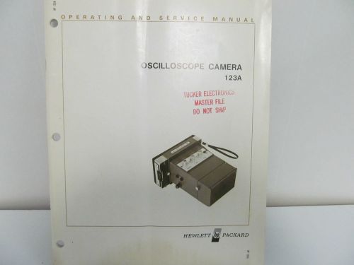
HP 123A Oscilloscope Camera Operating & Service Manual w/schematics
HP 130A Oscilloscope Operating & Service Manual w/schematics
HP Agilent 8082A 250MHz Pulse Generator
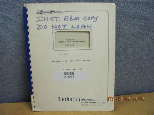
BERKELEY MODEL 4904: Double Pulse Generator - Instruction Manual schematic 17924
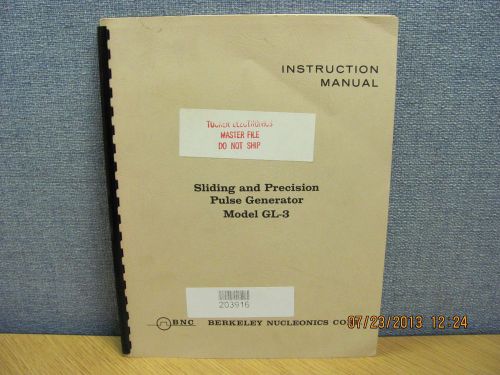
BERKELEY MODEL GL-3: Sliding&Precision Pulse Generator- Instruction Manual 17954
BECKMAN MODEL 3020: Pulse Delay Control - Instruction Manual #16901 COPY
BECKMAN MODEL 3021: Pulse Delay Control - Instruction Manual schem #16903 COPY
ANRITSU 680XXB/681XXB Synthesized CW/Sweep Generators - Revision D
ANRITSU 680XXB/681XXB Synthesized CW/Sweep Generators - Revision F
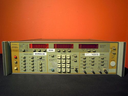
Wiltron 6624A Programmable Sweep Generator Opts.01/9N
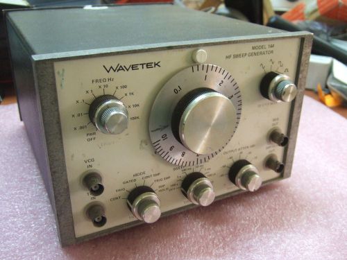
Wavetek 144 HF Sweep Generator
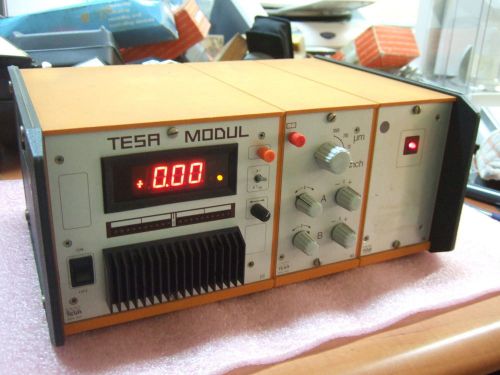
TESA MODUL 372 Digital Display Unit + 403 Module + 708 Module
By clicking "Accept All Cookies", you agree to the storing of cookies on your device to enhance site navigation, analyze site usage, and assist in our marketing efforts.
Accept All Cookies