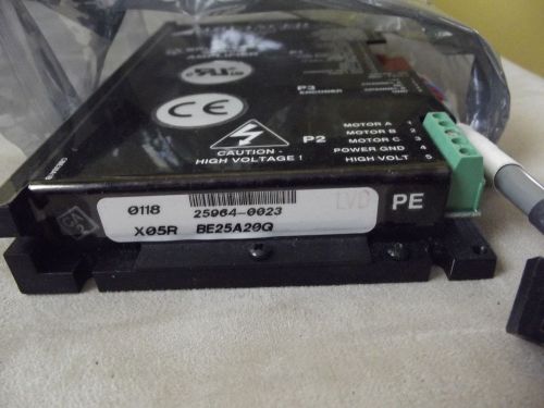
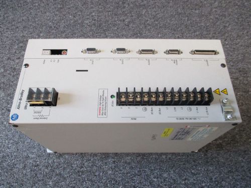
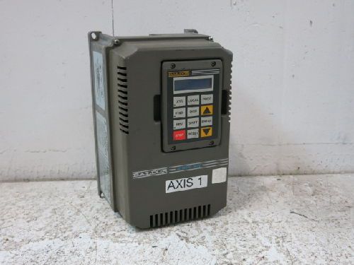
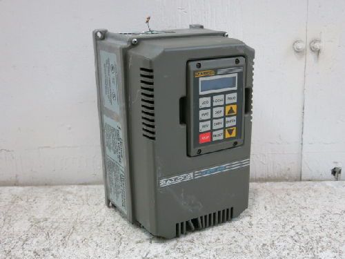
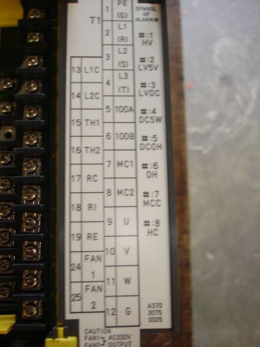
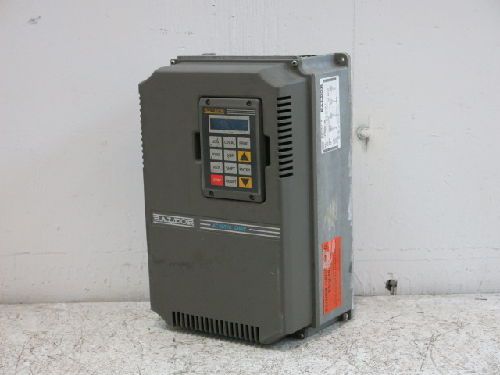
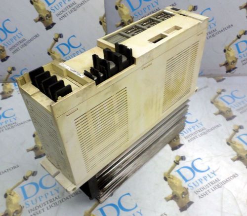
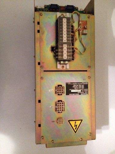
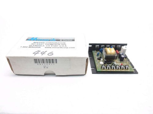
Servo Amp Advanced Motion Control Servo Amplifier Drive BE25A20H Drives brushless motors. Great for automation projects. Multiples of this unit available contact me if your interested. Comes with Molex connection cable If you would like more than one contact me. Advanced Motion Controls BE25A20H Brushless Servo Amplifier From our inventory, we are selling a Advanced Motion Controls BE25A20G Brushless Servo Amplifier. Specifications: Model #: BE25A20 More Information: LINK Peak Current: 25A Continuous Current: 12.5A Supply Voltage: 40-190VDC Payment Types We are only allowed to accept PayPal as payment per eBay’s policy. However, you can use a Credit Card through PayPal as a “one time payment”. Paying w/o a Paypal Account Combining Items Almost all orders can be combined, please contact us if you are bidding on multiple items that end on different days. That way we can invoice you correctly. When purchasing multiple quantities of the same item, select the amount you want, click buy it now, confirm your purchases, and then when you are done buying all of your items ask for a total and then we will send you an invoice to pay Condition: Excellent cosmetic condition with some signs of previous use (See photos for more details). Tested: Unit was removed from a working environment. Warranty: 14-Day Right-of-Return Great for CNC Automation Supplier data sheet: The BE25A20G PWM servo drive is designed to drive brushless DC motors at a high switching frequency. A single red/green LED indicates operating status. The drive is fully protected against over-voltage, under voltage, over-current, over-heating and short-circuits across motor, ground and power leads. Furthermore, the drive can interface with digital controllers or be used stand-alone, and requires only a single unregulated DC power supply. Loop gain, current limit, input gain and offset can be adjusted using 14- turn potentiometers. The offset adjusting potentiometer can also be used as an on-board input signal for testing purposes. This drive can use quadrature encoder inputs for velocity control. Features Four Quadrant Regenerative Operation DIP Switch Selectable Modes Adjustable Current Limits Differential Input Command On-Board Test Potentiometer Offset Adjustment Potentiometer Adjustable Input Gain Selectable 120/60 Hall Commutation Phasing DIP Switch Selectable Tuning Encoder Velocity Mode Drive Status LED Velocity Monitor Outputs MODES OF OPERATION Current Open Loop Encoder Velocity Tachometer Velocity COMMAND SOURCE ±10 V Analog FEEDBACK SUPPORTED Halls Incremental Encoder Tachometer COMPLIANCES & AGENCY APPROVALS UL cUL CE Class A (LVD) CE Class A (EMC) RoHS Release Date: 10/29/2009 Revision: 2.00 Page 1 of 9 Analog Servo Drive BE25A20 BLOCK DIAGRAM Information on Approvals and Compliances US and Canadian safety compliance with UL 508c, the industrial standard for power conversion electronics. UL registered under file number E140173. Note that machine components compliant with UL are considered UL registered as opposed to UL listed as would be the case for commercial products. Compliant with European CE for both the Class A EMC Directive 89/336/EEC on Electromagnetic Compatibility (specifically EN 61000-6-4:2001, EN 61000-6-2:2001, EN 61000-3-2:2000, and EN 61000-3-3:1995/A1:2001) and LVD requirements of directive 73/23/EEC (specifically EN 60204-1), a low voltage directive to protect users from electrical shock. RoHS (Reduction of Hazardous Substances) is intended to prevent hazardous substances such as lead from being manufactured in electrical and electronic equipment. Release Date: 10/29/2009 Revision: 2.00 Advanced Motion Controls · 3805 Calle Tecate, Camarillo, CA, 93012 ph# 805-389-1935 · fx# 805-389-1165· www.a-m-c.com Analog Servo Drive BE25A20 Release Date: 10/29/2009 Revision: 2.00 Advanced Motion Controls · 3805 Calle Tecate, Camarillo, CA, 93012 ph# 805-389-1935 · fx# 805-389-1165· SPECIFICATIONS Power Specifications Description Units Value DC Supply Voltage Range VDC 40 - 190 DC Bus Over Voltage Limit VDC 195 Maximum Peak Output Current1 A 25 Maximum Continuous Output Current A 12.5 Maximum Power Dissipation at Continuous Current W 119 Minimum Load Inductance (Line-To-Line)2 µH 250 Switching Frequency kHz 22 Control Specifications Description Units Value Command Sources - ±10 V Analog Feedback Supported - Halls, Incremental Encoder, Tachometer Commutation Methods - Trapezoidal Modes of Operation - Current, Encoder Velocity, Open Loop, Tachometer Velocity Motors Supported - Brushed, Brushless, Voice Coil Hardware Protection - Invalid Commutation Feedback, Over Current, Over Temperature, Over Voltage, Short Circuit (Phase-Phase & Phase-Ground) Mechanical Specifications Description Units Value Agency Approvals - CE Class A (EMC), CE Class A (LVD), cUL, RoHS, UL Size (H x W x D) mm (in) 186.7 x 111.7 x 25.4 (7.4 x 4.4 x 1) Weight g (oz) 680 (24) Heatsink (Base) Temperature Range3 °C (°F) 0 - 65 (32 - 149) Storage Temperature Range °C (°F) -40 - 85 (-40 - 185) Form Factor - Stand Alone P1 Connector - 16-pin, 2.54 mm spaced, friction lock header P2 Connector - 5-port, 5.08 mm spaced, screw terminal P3 Connector - 5-pin, 2.54 mm spaced, friction lock header Notes 1. Maximum duration of peak current is ~2 seconds. 2. Lower inductance is acceptable for bus voltages well below maximum. Use external inductance to meet requirements. 3. Additional cooling and/or heatsink may be required to achieve rated performance. Analog Servo Drive BE25A20 PIN FUNCTIONS P1 - Signal Connector Pin Name Description / Notes I/O 1 +10V 3mA OUT O 2 SIGNAL GND GND 3 -10V 3mA OUT ±10 V @ 3 mA low power supply for customer use. Short circuit protected. Reference ground common with signal ground. O 4 +REF IN I 5 -REF IN Differential Reference Input (±10 V Operating Range, ±15 V Maximum Input) I 6 -TACH IN Negative Tachometer Input (Maximum ±60 V). Use signal ground for positive input. I 7 VEL MONITOR OUT Velocity Monitor. Analog output proportional to motor speed. In Encoder Velocity mode, output is proportional to the encoder line frequency. Encoder Velocity scaling is 22 kHz/V. O 8 CURR MONITOR OUT Current Monitor. Analog output signal proportional to the actual current output. Scaling is 4.1 A/V by default but may be reduced to half this value by setting DIP switch SW-3 to OFF (see Hardware Settings section below). Measure relative to signal ground. O 9 INHIBIT IN TTL level (+5 V) inhibit/enable input. Leave open to enable drive. Pull to ground to inhibit drive. Inhibit turns off all power devices. I 10 +V HALL 30mA OUT Low Power Supply For Hall Sensors (+6 V @ 30 mA). Referenced to signal ground. Short circuit protected. O 11 GND Signal Ground GND 12 HALL 1 I 13 HALL 2 I 14 HALL 3 Single-ended Hall/Commutation Sensor Inputs (+5 V logic level) I 15 CURRENT REF OUT Measures the command signal to the internal current-loop. This pin has a maximum output of ±7.25 V when the drive outputs maximum peak current. Measure relative to signal ground. O 16 FAULT OUT TTL level (+5 V) output becomes high when power devices are disabled due to at least one of the following conditions: inhibit, invalid Hall state, output short circuit, over voltage, over temperature, power-up reset. O P2 - Power Connector Pin Name Description / Notes I/O 1 MOTOR A Motor Phase A O 2 MOTOR B Motor Phase B O 3 MOTOR C Motor Phase C O 4 POWER GND Power Ground (Common With Signal Ground) GND 5 HIGH VOLTAGE DC Power Input I P3 - Feedback Connector Pin Name Description / Notes I/O 1 +5V Low Power Supply For Encoder (+5 V @ 150 mA). Referenced to signal ground. Short circuit protected. O 2 CHANNEL A Single-ended encoder channel A input. +5 V logic level. I 3 NC Not Connected (Reserved) - 4 CHANNEL B Single-ended encoder channel B input. +5 V logic level. I 5 SIGNAL GND Signal Ground GND Analog Servo Drive BE25A20 Release Date: 10/29/2009 Revision: 2.00 Advanced Motion Controls · 3805 Calle Tecate, Camarillo, CA, 93012 ph# 805-389-1935 · fx# 805-389-1165· HARDWARE SETTINGS Switch Functions Setting Switch Description On Off 1 Test/Offset. Switches the function of the Test/Offset pot between an on-board command input for testing or a command offset adjustment. OFF by default. Test Offset 2 Current loop proportional gain adjustment. ON by default. Decrease Increase 3 Current scaling. When OFF, increases sensitivity of current sense thus reducing both peak and continuous current limit by 50%. The scaling of the current monitor output signal becomes 1/2 its ordinary value when this switch is OFF. Full-current Half-current 4 Outer loop integration. Activates or deactivates integration. ON, by default, for current mode and OFF for other modes. Inactive Active 5 Mode selection. See mode selection table below. - - 6 Mode selection. See mode selection table below. - - 7 Velocity feedback polarity. Changes the polarity of the internal feedback signal and the velocity monitor output signal. Inversion of the feedback polarity may be required to prevent a motor run- away condition. Standard Inverted 8 Current ratio. Used to set continuous-to-peak current ratio. Default is ON. Cont./Peak Ratio = 50% Cont./Peak Ratio = 25% 9 Outer loop integral gain adjustment. It is recommended to leave this switch OFF for most applications. Decrease Increase 10 Hall sensor phasing. Selects 120°/60° commutation phasing. ON by default. 120° 60° Mode Selection Table Mode SW2 SW4 SW5 SW6 Encoder Tachometer CURRENT ON ON OFF OFF Not Connected Not Connected OPEN LOOP ON OFF ON OFF Not Connected Not Connected ENCODER VELOCITY* ON OFF OFF ON Connected Not Connected TACHOMETER VELOCITY ON OFF OFF OFF Not Connected Connected *NOTE: See details of switch 7 for further Encoder Velocity configuration information. Potentiometer Functions Potentiometer Description Turning CW 1 Loop gain adjustment for open loop / velocity modes. Turn this pot fully CCW in current mode. Increases gain 2 Current limit. It adjusts both continuous and peak current limit while maintaining their ratio. Increases limit 3 Reference gain. Adjusts the ratio between input signal and output variables (voltage, current, or velocity). Increases gain 4 Offset / Test. Used to adjust any imbalance in the input signal or in the amplifier. Can also be used as an on-board signal source for testing purposes. Adjusts offset in negative direction Note: Potentiometers are approximately linear and have 12 active turns with 1 inactive turn on each end. Analog Servo Drive BE25A20 Release Date: 10/29/2009 Revision: 2.00 Advanced Motion Controls · 3805 Calle Tecate, Camarillo, CA, 93012 ph# 805-389-1935 · fx# 805-389-1165· Through-hole Components† Location Description C67* Velocity Loop Integrator. Through-hole capacitor that can be added for more precise velocity loop tuning. See section below on Tuning with Through-hole components for more details. C69* Current Loop Integrator. Through-hole capacitor that can be added for more precise current loop tuning. See section below on Tuning with Through-hole components for more details. R26* Current Loop Proportional Gain. Through-hole resistor that can be added for more precise current loop tuning. See section below on Tuning with Through-hole components for more details. Tuning With Through-hole Components In general, the drive will not need to be further tuned with through-hole components. However, for applications requiring more precise tuning than what is offered by the potentiometers and dipswitches, the drive can be manually modified with through-hole resistors and capacitors as denoted in the above table. By default, the through-hole locations are not populated when the drive is shipped. Before attempting to add through-hole components to the board, consult the section on loop tuning in the installation notes on the manufacturer’s website. Some general rules of thumb to follow when adding through-hole components are: • A larger resistor value will increase the proportional gain, and therefore create a faster response time. • A larger capacitor value will increase the integration time, and therefore create a slower response time. Proper tuning using the through-hole components will require careful observation of the loop response on a digital oscilloscope to find the optimal through-hole component values for the specific application. †Note: Damage done to the drive while performing these modifications will void the warranty. Analog Servo Drive BE25A20 MECHANICAL INFORMATION P1 - Signal Connector Connector Information 16-pin, 2.54 mm spaced, friction lock header Details Molex: P/N 22-01-3167 (connector) and P/N 08-50-0114 (insert terminals) Mating Connector Included with Drive Yes +10V 3mA OUT1 SIGNAL GND2 -10V 3mA OUT3 +REF IN4 -REF IN5 -TACH IN6 VEL MONITOR OUT7 CURR MONITOR OUT8 INHIBIT IN9 +V HALL 30mA OUT10 GND11 HALL 112 HALL 314 FAULT OUT16 HALL 213 CURRENT REF OUT15 P2 - Power Connector Connector Information 5-port, 5.08 mm spaced, screw terminal Details Not applicable Mating Connector Included with Drive Not applicable MOTOR A1 MOTOR B2 MOTOR C3 POWER GND4 HIGH VOLTAGE5 P3 - Feedback Connector Connector Information 5-pin, 2.54 mm spaced, friction lock header Details Molex: P/N 22-01-3167 (connector) and P/N 08-50-0114 (insert terminals) Mating Connector Included with Drive Yes +5V1 CHANNEL A2 NC3 CHANNEL B4 SIGNAL GND5 Release Date: 10/29/2009 Revision: 2.00 Advanced Motion Controls · 3805 Calle Tecate, Camarillo, CA, 93012 ph# 805-389-1935 · fx# 805-389-1165· www.a-m-c.com Page 7 of 9 Analog Servo Drive BE25A20 \ MOUNTING DIMENSIONS Release Date: 10/29/2009 Revision: 2.00 Advanced Motion Controls · 3805 Calle Tecate, Camarillo, CA, 93012 ph# 805-389-1935 · fx# 805-389-1165· Analog Servo Drive BE25A20 PART NUMBERING INFORMATION A Peak Voltage Peak Current 20 - Additional Options B or BX: Brushless drive. Maximum peak current rating in Amps. Peak voltage rating scaled 1:10 in Volts. Power Supply : DC Power Supply Drive Type BE: Encoder Velocity Mode Available BD: PWM Command BDC: PWM Command, Closed Current Loop S or SX: Commutated Sine Command Revision Assigned a letter (A through Z) by manufacturer. AC: AC Power Supply FAC: AC Power Connecter Relocated to the Front I: Optical Isolation Isolation Option 25BE ADVANCED Motion Controls servo drives are available in many configurations. All models listed in the selection tables of the website are readily available, standard product offerings. ADVANCED Motion Controls also has the capability to promptly develop and deliver specified products for OEMs with volume requests. Our Applications and Engineering Departments will work closely with your design team through all stages of development in order to provide the best servo drive solution for your system. Equipped with on-site manufacturing for quick- turn customs capabilities, ADVANCED Motion Controls utilizes our years of engineering and manufacturing expertise to decrease your costs and time-to-market while increasing system quality and reliability. Examples of Customized Products Integration of Drive into Motor Housing Integrate OEM Circuitry onto Drive PCB Mount OEM PCB onto Drive Without Cables Custom Control Loop Tuned to Motor Characteristics Multi-axis Configuration for Compact System Custom I/O Interface for System Compatibility Custom PCB and Baseplate for Optimized Footprint Preset Switches and Pots to Reduce User Setup RTV/Epoxy Components for High Vibration Optimized Switching Frequency OEM Specified Connectors for Instant Compatibility Ramped Velocity Command for Smooth Acceleration OEM Specified Silkscreen for Custom Appearance Remove Unused Features to Reduce OEM Cost Increased Thermal Limits for High Temp. Operation Application Specific Current and Voltage Limits Feel free to contact Applications Engineering for further information and details. Available Accessories ADVANCED Motion Controls offers a variety of accessories designed to facilitate drive integration into a servo system. Visit www.a-m-c.com to see which accessories will assist with your application design and implementation. Power Supplies Shunt Regulators Filter Cards Release Date: 10/29/2009 Revision: 2.00 Advanced Motion Controls · 3805 Calle Tecate, Camarillo, CA, 93012 ph# 805-389-1935 · fx# 805-389- Other Ebay sellers are selling this same unit for $215 plus shipping and have told me that I am flooding the market.
By clicking "Accept All Cookies", you agree to the storing of cookies on your device to enhance site navigation, analyze site usage, and assist in our marketing efforts.