
US $6400
| Condition: |
Used: An item that has been used previously. The item may have some signs of cosmetic wear, but is fully
operational and functions as intended. This item may be a floor model or store return that has been used. See the seller’s listing for full details and description of any imperfections.
...
|
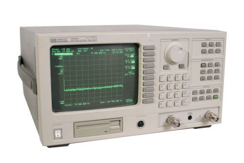
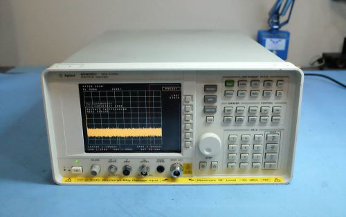
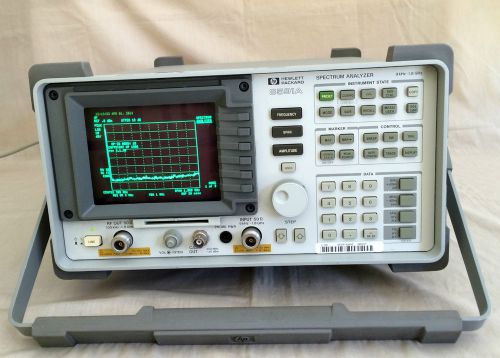
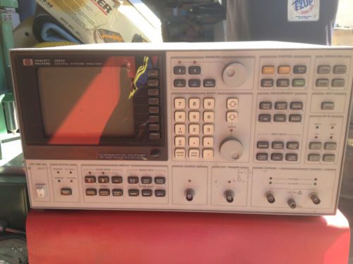
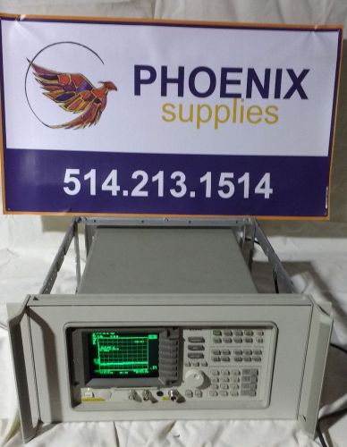
Brand | HP |
| Model | 3589A |
Directions
Similar products from Spectrum Analysis Systems
HP / Agilent 8594E Spectrum Analyzer
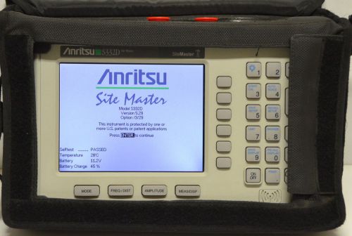
Anritsu S332D SiteMaster Cable/Antenna & Spectrum Analyzer w/Opt 29 Phase Cable
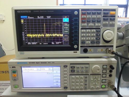
GA4063 Spectrum Analyzer, 9KHz to 3 GHz, LAN,USB,RS-232 + Pre-Amp.
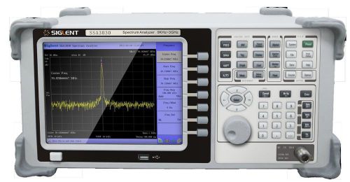
SSA3030 Spectrum Analyzer, 9KHz to 3 GHz, include : LAN,USB,RS-232 + VGA output
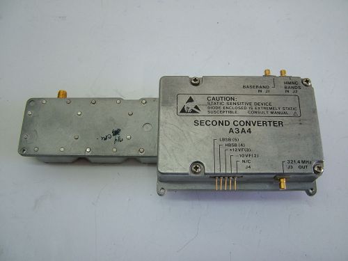
HP A3A4 SECOND CONVERTER 5021-7475 FOR 8592A SA
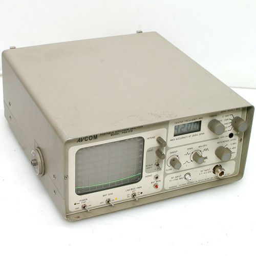
AVCOM PSA-37D 4.2GHz Portable Spectrum Analyzer for Parts Tunes Signal Dented In
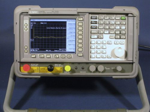
Keysight/Agilent E4407B/1DN/1D5/1DR/1DS/A4H/AYX/BAA/UKB/120/219 9 KHz – 26.5 GHz
HP 8560EC 30Hz-2.9GHz Spectrum Analyzer, Opt 007
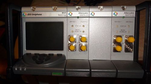
JDS Uniphase MAP+2B00 / with 2 precision optical attenuators MAPA+23
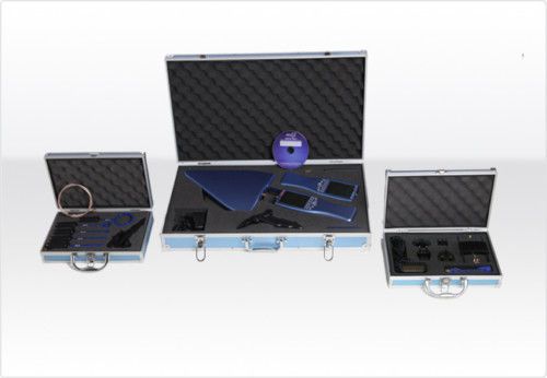
EMC measurement set - Spectrum Analyzer Bundle 1Hz-9GHz
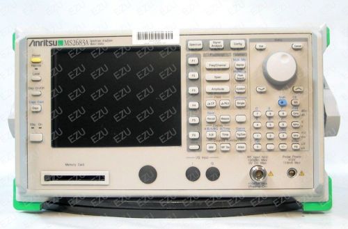
Anritsu MS2683A - 03 Spectrum Analyzer, 9 kHz to 7.8 GHz
IFR Marconi AeroFlex A-7550 Spectrum Analyzer 10kHz to 1GHz -c
Agilent / HP 8591A Spectrum Analyzer w/ Tracking Generator, 1.8GHz, OPT 010, 021
Keysight E4443A PSA Spectrum Analyzer, 3 Hz - 6.7 GHz (Agilent E4443A)
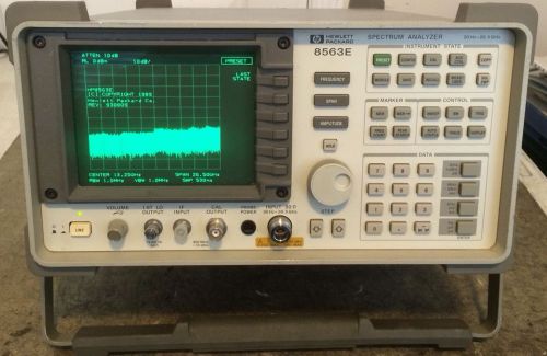
HP 8563E Spectrum Analyzer 30 Hz To 26.5 GHz
ROHDE & SCHWARZ FSH3 FSH3.03 FSH-03 SPECTRUM ANALYZER 100KHZ-3GHZ FREQ RANGE
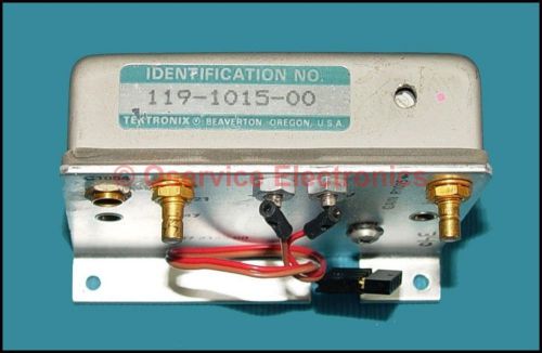
Tektronix 119-1015-00 Amplifier-Filter AssemblY for 495 Series Spectrum Analyzer
People who viewed this item also vieved
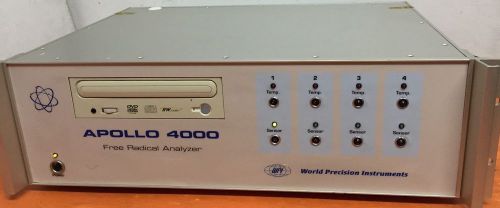
WORLD PRECISION INSTRUMENTS APOLLO 4000 FREE RADICAL ANALYZER
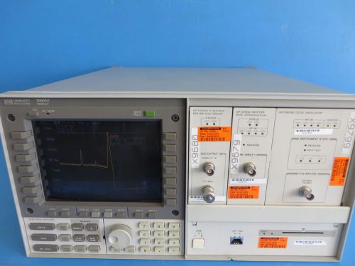
HP 70004A Spectrum Analyzer w/ 70902A 70700A 70900B Modules
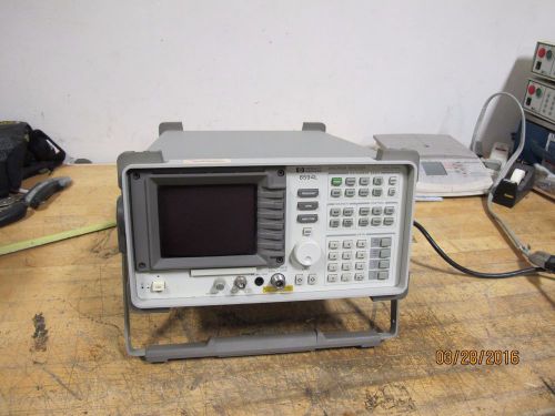
HP Agilent-Keysight 8594L RF Spectrum Analyzer (9 kHz to 2.9 GHz) OPTION 041

HP Agilent 89410A Vector Signal Analyzer 10MHz
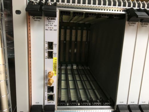
JDSU TESTPOINT TS-170 17-SLOT MAINFRAME CHASSIS+ N530-0134 MODULE
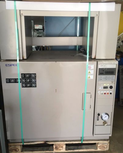
TABAI ESPEC Environmental Temperature Chamber Model PHH-201
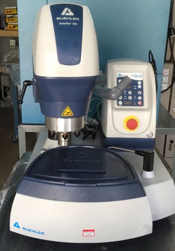
Buehler AutoMet 250 Digital Lab Grinder Polisher 10"
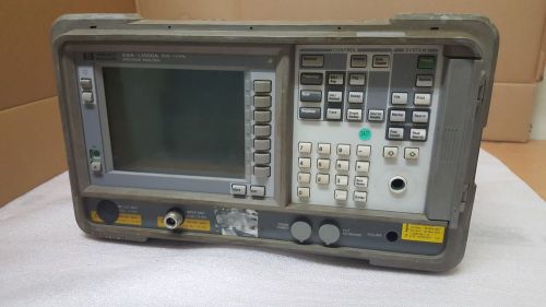
Agilent HP ESA-L1500A 9KHz - 1.5 GHz Spectrum Analyzer
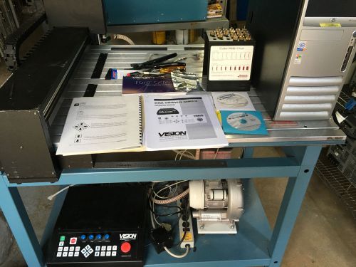
Vision 2424 Engraving and Routing and Systems COMPLETE
Agilent/HP 8594E 9kHz to 2.9 GHz Spectrum Analyzer OPT 041, 101, 103, 140 85700a
By clicking "Accept All Cookies", you agree to the storing of cookies on your device to enhance site navigation, analyze site usage, and assist in our marketing efforts.
Accept All Cookies