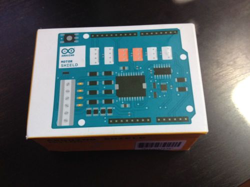
Description Nice used condition Arduino Motor Shield. Genuine arduino unit. In original box. Guaranteed to be fully functional. Overview The Arduino Motor Shield is based on the L298 (datasheet), which is a dual full-bridge driver designed to drive inductive loads such as relays, solenoids, DC and stepping motors. It lets you drive two DC motors with your Arduino board, controlling the speed and direction of each one independently. You can also measure the motor current absorption of each motor, among other features. The shield is TinkerKit compatible, which means you can quickly create projects by pluggingTinkerKit modules to the board. Summary Operating Voltage5V to 12V Motor controllerL298P, Drives 2 DC motors or 1 stepper motor Max current2A per channel or 4A max (with external power supply) Current sensing1.65V/A Free running stop and brake function Schematic & Reference Design EAGLE files: arduino_MotorShield_Rev3-reference-design.zip http://arduino.cc/en/uploads/Main/arduino_MotorShield_Rev3.zip Schematic: arduino_MotorShield_Rev3-schematic.pdf http://arduino.cc/en/uploads/Main/arduino_MotorShield_Rev3-schematic.pdf Power The Arduino Motor Shield must be powered only by an external power supply. Because the L298 IC mounted on the shield has two separate power connections, one for the logic and one for the motor supply driver. The required motor current often exceeds the maximum USB current rating. External (non-USB) power can come either from an AC-to-DC adapter (wall-wart) or battery. The adapter can be connected by plugging a 2.1mm center-positive plug into the Arduino's board power jack on which the motor shield is mounted or by connecting the wires that lead the power supply to the Vin and GND screw terminals, taking care to respect the polarities. To avoid possible damage to the Arduino board on which the shield is mounted, we reccomend using an external power supply that provides a voltage between 7 and 12V. If your motor require more than 9V we recommend that you separate the power lines of the shield and the Arduino board on which the shield is mounted. This is possible by cutting the "Vin Connect" jumper placed on the back side of the shield. The absolute limit for the Vin at the screw terminals is 18V. The power pins are as follows Vin on the screw terminal block, is the input voltage to the motor connected to the shield. An external power supply connected to this pin also provide power to the Arduino board on which is mounted. By cutting the "Vin Connect" jumper you make this a dedicated power line for the motor. GND Ground on the screw terminal block. The shield can supply 2 amperes per channel, for a total of 4 amperes maximum. Input and Output This shield has two separate channels, called A and B, that each use 4 of the Arduino pins to drive or sense the motor. In total there are 8 pins in use on this shield. You can use each channel separately to drive two DC motors or combine them to drive one unipolar stepper motor. The shield's pins, divided by channel are shown in the table below Functionpins per Ch. Apins per Ch. B DirectionD12D13 PWMD3D11 BrakeD9D8 Current SensingA0A1 If you don't need the Brake and the Current Sensing and you also need more pins for your application you can disable this features by cutting the respective jumpers on the back side of the shield. The additional sockets on the shield are described as follow: Screw terminal to connect the motors and their power supply. 2 TinkerKit connectors for two Analog Inputs (in white), connected to A2 and A3. 2 TinkerKit connectors for two Aanlog Outputs (in orange in the middle), connected to PWM outputs on pins D5 and D6. 2 TinkerKit connectors for the TWI interface (in white with 4 pins), one for input and the other one for output. Motors connections Brushed DC motor. You can drive two Brushed DC motors by connecting the two wires of each one in the (+) and (-) screw terminals for each channel A and B. In this way you can control its direction by setting HIGH or LOW the DIR A andDIR B pins, you can control the speed by varying the PWM A and PWM B duty cycle values. The Brake A and Brake Bpins, if set HIGH, will effectively brake the DC motors rather than let them slow down by cutting the power. You can measure the current going through the DC motor by reading the SNS0 and SNS1 pins. On each channel will be a voltage proportional to the measured current, which can be read as a normal analog input, through the function analogRead() on the analog input A0 and A1. For your convenience it is calibrated to be 3.3V when the channel is delivering its maximum possible current, that is 2A. Physical Characteristics The maximum length and width of the Motor Shield PCB are 2.7 and 2.1 inches respectively. Four screw holes allow the board to be attached to a surface or case. Note that the distance between digital pins 7 and 8 is 160 mil (0.16"), not an even multiple of the 100 mil spacing of the other pins. About mp3car Founded in 1998, mp3Car has been a pioneering force in the mobile computing world; the accomplishments of our company and our community are a vibrant proof-of-concept for the potential of mobile computing. Within a year of its inception, our web-ring evolved into the mp3car.com Forums, which now host well over 100,000 members, comprising hardware engineers, software developers, car audiophiles, automotive installers and vendors. This collaborative environment helps us identify and solve real-world problems, and forms the backbone of our novel research and development style. The direct consequences of our efforts can be felt every day. We were popularizing mp3 players in automobiles two years before the appearance of the iPod; not only was this one of many times we advanced the industry by employing mobile technology in a ground-breaking way, it’s also how we got our name. Shipping New condition item orders are processed within 1 business day. You will receive an email with tracking information from eBay once your item ships. If you don't receive this email, you can log into your eBay or Paypal account and view tracking information there. Please note that you are responsible for all import fees and taxes upon delivery of your package. Used condition items are shipped within 3 business days. Whitebox Guarantee Every new item we sell includes a 30 day money-back guarantee. In addition, most products include at least a limited 1 year warranty, serviceable through us or the manufacturer directly. We strive for 100% customer satisfaction. If you're not happy with your product or purchase experience, please contact us and let us make it right for you. About Whitebox Whitebox is a Maryland-based company focused on bringing high-quality products to market from small to medium-sized manufacturing and sourcing firms. Exemplary customer service is the backbone of the Whitebox mission. We guarantee all of our customers get what they order on time and in exceptional condition. Have a product to sell? Let us do the eCommerce side of your business for you so you can stay focused on what you love: designing and manufacturing products. Contact Whitebox You can contact us all the time through the eBay message system. We guarantee responses within 1 business day. Most responses take only a few hours.
By clicking "Accept All Cookies", you agree to the storing of cookies on your device to enhance site navigation, analyze site usage, and assist in our marketing efforts.