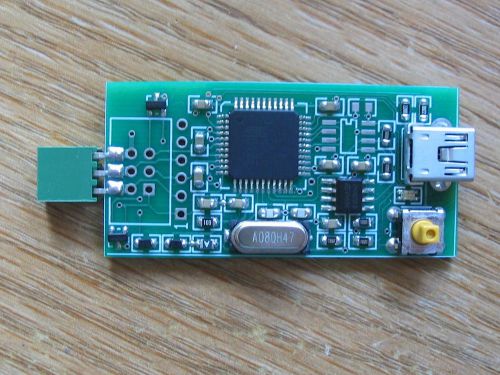
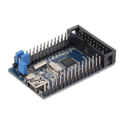
This is V1 of this product and it can do ISP (TINY/MEGA) programming from 62.5kHz to 2MHz. This board has 128KB in EEPROM, but the software supports compression so you can fit more than 128KB on it. 128KB should cover most TINY/MEGA devices with ease, but there is a second EEPROM slot where you can add more EEPROM if you need to (64K/128K/256K). It has a 2x3 female ISP connector to plug directly to a standard 2x3 male ISP header. I am clearing these out to make room for the newer V3 version that does both ISP (TINY/MEGA) and PDI protocols (XMEGA), but if you only need ISP programming, this is a deal! There is no other AVR programmer like this, you might find another standalone one, but it will not have the matching ability and multiple AVR/multiple firmware ability that this one has. You can download the full manual here: Manual You can download the PC application here: PC application This tiny board is a fully automated programmer. The original intent of this device was to update a product in the field by someone unfamiliar with programming. It requires only that someone can line up pin 1 (you could send a picture showing the right way to connected it) and turn it on. The autoprogrammer does the rest. Its small size makes it very low cost to send out in a bubble envelope. You can even include a smaller return addressed stamped envelope to get it back when the customer is done using it. I found that it also excels at in house production programming. It is so much more convenient to grab it and connect it to a board than it is to either take that board to a PC or bring a PC or notebook to the board. For this reason, another use is also that it can easily go where taking a PC or notebook might be difficult or impractical. It is set apart from other self contained programmers because it has a multiple microcontroller multiple firmware configuration capability. This allows for a single autoprogrammer with a single loaded configuration to handle multiple projects, different firmware versions or variants of the same project, and/or different AVR variants that need the same firmware all at the same time. It supports flashing 2.7V-5V targets and acquires power from the programming header. Support up to 512KB EEPROM in two banks. Can support either a female connector to direct plug or a male connector to use a 2x3 IDC ribbon cable. It is so handy you won’t even believe how much you use it! It is faster for me to load up the pc application and create a configuration to do programming than it is for me to drag my notebook into another room. Detailed Features: Standalone programming does not require PC. ISP protocol support from 62.5 kHz to 2 MHz. Fully automated programming requires no interaction from end user – you can send the device to anyone and all they have to do is plug it in and turn it on. Multiple microcontroller multiple firmware configuration allows a single configuration to carry out multiple tasks. A matching process allows you to match a device by its device signature and optionally any fuse or lockbits to a particular firmware you want it to flash. One way this can be used is to have a single configuration update completely different devices. You could send one autoprogrammer to your customer and it can update 4 different products or different AVR’s in the same product. Another benefit is that it can be used to handle different variants of the same basic AVR. You might have a product that was built with both ATMEGA328 and ATMEGA328P and each has its own device signature. Simply match both devices and point them to the same firmware to update and it will flash whichever it encounters. For in house production programming, I often have a need to flash two different versions of firmware for the same device. If I create a configuration where more than one match is possible, it will prompt me to select which one I wish to flash (V1 or V3, but not V2). See the example sections at the end of this manual for various configurations you could use. An flash limit can be set to only allow a specific number of flashes for each firmware. You can also restrict the matching to only update a device that has the expected device signature, expected fuses, and expected lockbits settings. It keeps track of the number of successful flashes for each firmware; this information can be later retrieved using the pc application. It can program flash and EEPROM, or program and verify flash and EEPROM. Fuse and lock its settings are always programmed and verified. Programming settings are built in for these devices: AT90CAN128, AT90CAN32, AT90CAN64, AT90PWM[1|2B|3B], AT90PWM[216|316], AT90PWM161, AT90PWM81, AT90USB[1286|1287], AT90USB[646|647], AT90USB162, AT90USB82, ATmega128[A], ATmega1280, ATmega1281, ATmega1284, ATmega1284P, ATmega1284RFR2, ATmega128RFA1, ATmega128RFR2, ATmega16[A], ATmega162, ATmega164A, ATmega164P[A], ATmega165A, ATmega165P[A], ATmega168[A], ATmega168P[A], ATmega169A, ATmega169P[A], ATmega16HVA, ATmega16HVB[REVB], ATmega16M1, ATmega16U2, ATmega16U4, ATmega2560, ATmega2561, ATmega32[A], ATmega324A, ATmega324P, ATmega324PA, ATmega325[A], ATmega3250[A], ATmega3250P[A], ATmega325P[A], ATmega328, ATmega328P, ATmega329[A], ATmega3290[A], ATmega3290P[A], ATmega329P[A], ATmega32C1, ATmega32HVB[REVB], ATmega32M1, ATmega32U2, ATmega32U4, ATmega48[A], ATmega48P[A], ATmega64[A], ATmega640, ATmega644[A], ATmega644P[A], ATmega644RFR2, ATmega645[A], ATmega6450[A], ATmega6450P, ATmega645P, ATmega649[A], ATmega6490[A], ATmega6490P, ATmega649P, ATmega64C1, ATmega64HVE2, ATmega64M1, ATmega64RFR2, ATmega8[A], ATmega8515, ATmega8535, ATmega88[A], ATmega88P[A], ATmega8HVA, ATmega8U2, ATtiny13[A], ATtiny1634, ATtiny167, ATtiny2313[A], ATtiny24[A], ATtiny25, ATtiny26, ATtiny261[A], ATtiny4313, ATtiny43U, ATtiny44[A], ATtiny45, ATtiny461[A], ATtiny48, ATtiny828, ATtiny84[A], ATtiny85, ATtiny861[A], ATtiny87, ATtiny88, ATxmega128A1/ATxmega128A1U, ATxmega128A3/ATxmega128A3U, ATxmega128A4U, ATxmega128B1, ATxmega128B3, ATxmega128C3, ATxmega128D3, ATxmega128D4, ATxmega16A4/ATxmega16A4U, ATxmega16C4, ATxmega16D4, ATxmega16E5, ATxmega192A3/ATxmega192A3U, ATxmega192C3, ATxmega192D3, ATxmega256A3/ATxmega256A3U, ATxmega256A3B/ATxmega256A3BU, ATxmega256C3, ATxmega256D3, ATxmega32A4/ATxmega32A4U, ATxmega32C3, ATxmega32C4, ATxmega32D3, ATxmega32D4, ATxmega32E5, ATxmega384C3, ATxmega384D3, ATxmega64A1/ATxmega64A1U, ATxmega64A3/ATxmega64A3U, ATxmega64A4U, ATxmega64B1, ATxmega64B3, ATxmega64C3, ATxmega64D3, ATxmega64D4, ATxmega8E5 It can support for new or unknown devices by specifying a custom device signature, flash page size, and EEPROM page size. This will allow it to operate with devices that are not on the above list. New devices can be added to the above list in a PC software update without requiring a firmware update. If a failure occurs during the programming process including the final lock bits write and verify, a chip erase will occur and leave the device unprogrammed. Encryption is used for on board EEPROM as well as on disk configuration storage to prevent anyone from extracting code. Configurations can be uploaded to the board, verified, and tested, but not downloaded from the board. Flash or EEPROM images can be loaded into the configuration, but not saved. Everything is CRC protected to ensure data integrity and compression is supported for flash and EEPROM images to reduce configuration size. USB design uses no PC side driver for simplicity, just plug it in and start up the PC application to manage a board. USB protocol between PC application and board is also encrypted and CRC protected. It supports configuration storage of up to 512KB. There are two EEPROM banks for a 64KB, 128KB, or 256KB EEPROM each. Any size in any bank is valid. Board is dual powered. For device programming it is powered by the device being programmed and supports 2.7V-5V. To be programmed with a configuration, it is USB powered when plugged into a PC. It is not intended to be plugged into both USB and a target to program at the same time and will switch to USB mode. It also has components to protect a lower voltage target from USB voltage (5V). Board has a Red LED and a Green LED (V1 and V2) or a 5 segment Green LED Graph (V3) to indicate status. The Red LED will blink out a two digit error code if something goes wrong, and the Green LED(s) will indicate programming status. With the single Green LED (V1 and V2) when it goes solid, programming was successful. With the 5 segment Green LED Graph (V3) when all 5 segments areon solid, programming was successful. Board has extensive self test features for reliability. PC application can load and save configurations to disk. PC application allows to users to choose which protocols are enabled (ISP, PDI, or both) and the programming frequency for each firmware entry. PC application has an identification string that can be used to describe the contents of a configuration, what versions are included, etc. When identifying a board it will indicate the contents of this string so the user can know what it was programmed with. PC application shows the total configuration size. The user can use this to determine if their board has enough EEPROM to hold the configuration. PC application supports up to 250 microcontroller entries, each one identifying a microcontroller signature and fuses or lock bits to match it by. PC application supports up to 30 firmware entries, each one holding firmware, EEPROM, fuse, and lockbits settings. PC application loads HEX files, ELF files, or BIN files. ELF files can import flash, EEPROM, fuse, and lockbits settings at one time. PC application has single button tasks for board identification, program/verify/test, program, verify, test, quick erase, and secure erase. These buttons will automatically perform the action on all attached boards. PC application has an EEPROM fill feature which allows writing a single byte value to a specific number of bytes; this can be used to erase or set EEPROM even if the EESAVE fuse is enabled. PC application can handle multiple boards plugged in at the same time.
By clicking "Accept All Cookies", you agree to the storing of cookies on your device to enhance site navigation, analyze site usage, and assist in our marketing efforts.