US $39.00
Directions
Similar products from Instruction Manuals for Metal Cutting
Tricks & Secrets of Old Time Machinists 4: Lathe work hints (Lindsay howto book)
Haas Digital Indexing Head Model S5C Users Guide Manual *1086
Thermal Dynamics CutMaster 51 Plasma Cutter Operating Manual *989
Thermal Dynamics PakMaster 25 110 Volt Plasma Cutter Operating Manual *992
Thermal Dynamics Pakmaster 75XL Plasma Cutter Operating Manual *1000
Haas Indexing Head Model HA5C Operators Manual *1087
DeVlieg Operating Manual Spiramatic Jigmil "K" Series (Inv.18006)

The Kinematics of Machinery: Outlines of a Theory of Machines (1876) - reprint
Mori Seiki MV-55 45/40 & 45/45 CNC Vertical Machine Center Parts Manual
DoAll Model G-10 Surface Grinder Instruction Manual and Repalcement Parts List
STRIPPIT FABRICATOR SONIC 18/30 - SERVICE MANUAL
Documentation for the Hyundai Lathe 18S Siemens 840C
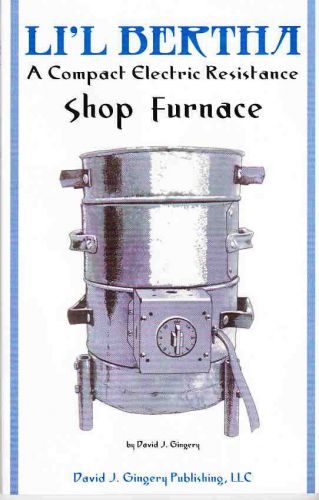
Li'l Bertha: An Electric Resistance Shop Furnace - Plans to Build it Yourself!
SCHAUBLIN 70 service instructions Metal Lathe Manual book
Lot Of 2 Leland-Gifford Drilling Machines Manual
CLAUSING 12" 5900 Series Variable SPD Lathe Operator & Part Manual <502100 0137
CLAUSING Colchester 11" 8000 Series Metal Lathe SERVICE & REPAIR Manual 1060
CLAUSING Colchester 13" 8000 Series Metal Lathe SERVICE & REPAIR Manual 1061
CLAUSING Colchester 15" 8000 Series Metal Lathe SERVICE & REPAIR Manual 1062
CLAUSING Colchester 17" 8000 Series Metal Lathe SERVICE & REPAIR Manual 1063
People who viewed this item also vieved
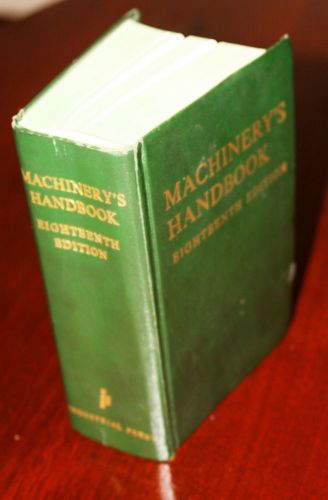
Machinery’s Handbook 18th Edition 1968 Excellent Condition
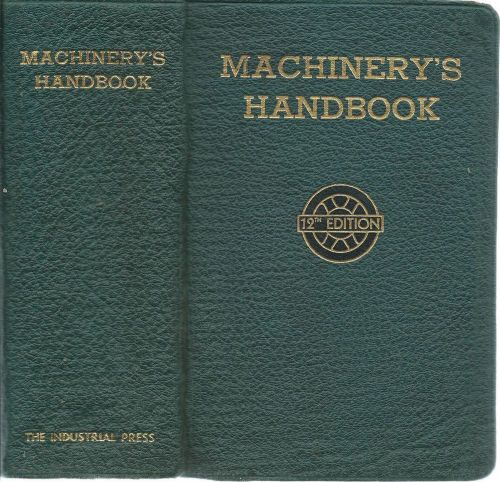
MACHINERY'S HANDBOOK - by Eric Oberg and F D Jones - 1943, 12th Ed.
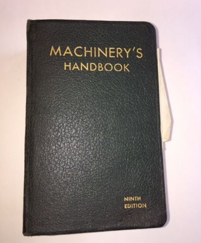
VINTAGE WAR TIME MACHINERY'S HANDBOOK 9th. EDITION 1937
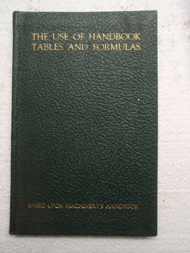
Use of Handbook Tables and Formulas Copyright 1931 1954
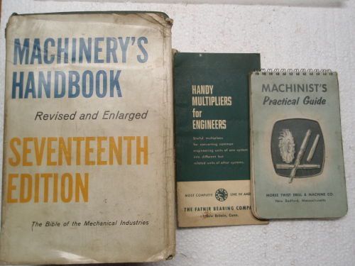
Machinerys Handbook 17th Edition + Machinists Practical Guide + More
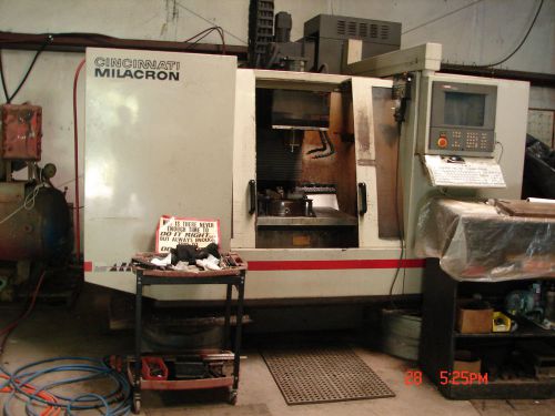
CNC Mill Model JVM 836-1 Cincinnati Milacron Arrow 750 ERO Mfg 1995
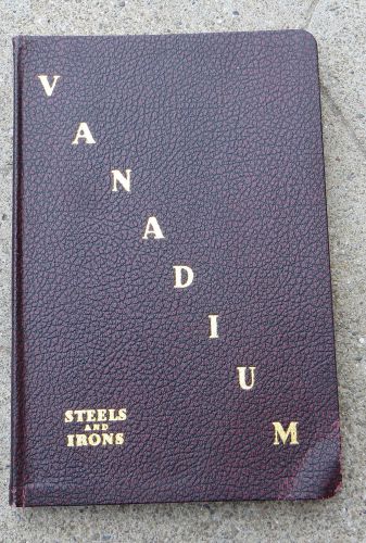
Vintage 1930s 1940s Vanadium Steels and Irons Book / Manual
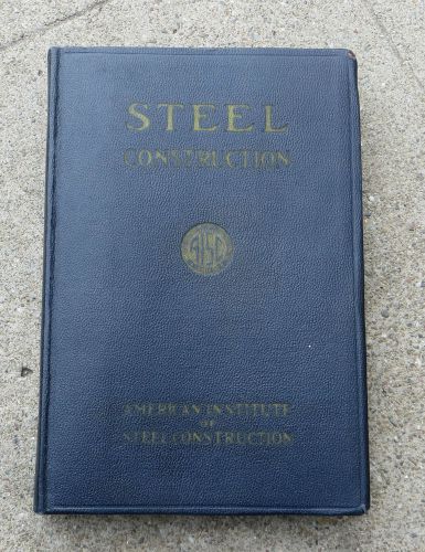
Vintage 1939 Steel Construction Book / Manual American Institute of Steel
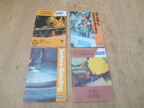
NORTON GRINDING BOOKS , THREAD, SURFACE INTERNAL AND O.D.GRINDING,
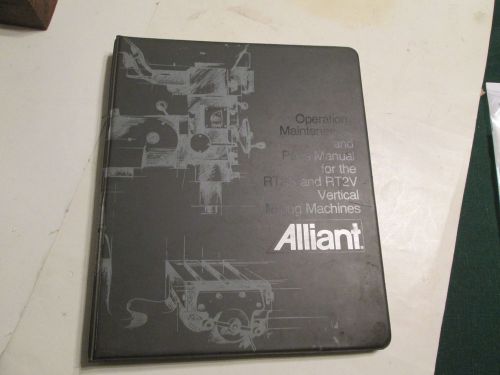
Alliant Milling Machine Manual Original NOT A COPY
By clicking "Accept All Cookies", you agree to the storing of cookies on your device to enhance site navigation, analyze site usage, and assist in our marketing efforts.
Accept All Cookies