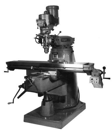
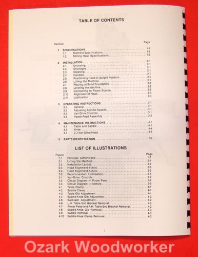
Untitled Document Free, Fast Shipping Every Business Day! See All Categories How-to Books Lathe Practices Series Lathe Operations Milling Operations Grinding Operations Metalworking Woodworking Brands Bridgeport Series II Special Vertical Milling Machine Instructions and Parts Manual Manual Description: Number of Pages: 55 This is a reproduction, not a photocopy, of an original Bridgeport Series II Special Vertical Milling Machine Instructions and Parts Manual. This manual contains information installation, operating instructions, lubrication, alignments and adjustments, maintenance, replacing the belts, wiring diagrams for the powerfeed, and parts diagams of all the parts with descriptions. Please read the contents below the picture for more information. Contents: 1 SPECIFICATIONS..................................1-1 1.1 Machine Specifications........................1-1 1.2 Milling Head Specifications...................1-2 2 INSTALLATION....................................2-1 2.1 Uncrating.....................................2-1 2.2 Shortages.....................................2-1 2.3 Cleaning......................................2-1 2.4 Handles.......................................2-1 2.5 Positioning Head in Upright Position..........2-1 2.6 Lifting the Machine...........................2-1 2.7 Placing on Solid Foundation...................2-2 2.8 Leveling the Machine..........................2-2 2.9 Connecting to Power Source....................2-2 2.10 Alignment of Head............................2-3 2.11 Lubrication..................................2-3 3 OPERATING INSTRUCTIONS..........................3-1 3.1 General.......................................3-1 3.2 Adjusting Spindle Speeds......................3-1 3.3 Vari-Drive Controls...........................3-1 3.4 Power Feed Assembly...........................3-3 4 MAINTENANCE INSTRUCTIONS........................4-1 4.1 Table and Saddle..............................4-1 4.2 Knee..........................................4-4 4.3 2 J Vari-Drive Head...........................4-5 5 PARTS IDENTIFICATION............................5-1 LIST OF ILLUSTRATIONS 1-1 Principal Dimensions..........................1-2 2-1 Lifting the Machine...........................2-1 2-2 Installation Layout...........................2-2 2-3 Head Alignment Y-Axis.........................2-3 2-4 Head Alignment X-Axis.........................2-3 2-5 Recommended Lubrication.......................2-4 3-1 Vari-Drive Controls...........................3-2 3-2 Circuit Diagram — Power Feed..................3-4 3-3 Circuit Diagram — Motors......................3-5 4-1 Table Clamp...................................4-1 4-2 Saddle Clamp..................................4-1 4-3 Table Gib Adjustment..........................4-1 4-4 Saddle-Knee Gib Adjustment....................4-2 4-5 Backlash Adjustment...........................4-2 4-6 L.H. Table End Bracket Removal................4-2 4-7 Power Feed and R.H. Table End Bracket Remova..4-2 4-8 Saddle-Knee Gib Removal.......................4-3 4-9 Saddle Removal................................4-3 4-10 Saddle-Knee Clamp Removal....................4-3 4-11 Knee Locking Mechanism.......................4-4 4-12 Knee Gib Adjustment..........................4-4 4-13 Knee Clamp Removal...........................4-4 4-14 Knee Elevating Shaft Assembly................4-5 4-15 Mounting Head................................4-5 4-16 Correcting Spindle Speed.....................4-6 4-17 Removing the Motor...........................4-7 4-18 Removing the Vari-Drive Belt.................4-8 4-19 Removing the HTD Belt........................4-8 5-1 Ram Installation..............................5-1 5-2 Front View — Basic Machine....................5-3 5-3 Side View — Basic Machine.....................5-5 5-4 Power Feed Assembly To Serial #1321...........5-7 5-5 Power Feed Assembly After Serial #1321........5-9 5-6 J Head Top Housing..... .....................5-11 5-7 J Head Assembly..............................5-13 5-8 2 J Head Top Housing.........................5-15 5-9 2 J Back Gear Assembly.......................5-17 5-10 M Head Assembly.............................5-19 5-11 Shaping Attachment Assembly.................5-21 5-12 Z-Axis Drive Pedestal Cylinder Assembly......5-2 Overview: I have collected this information for many years and have found the information they contain to be priceless in using and setting up the machines properly. I believe this manual will be a valuable resource of knowledge that will provide a lot of helpful information that is often hard to find. My manuals are not photocopies. I maintain a high standard of quality in my reproductions. Most of the manuals I reproduce look better than their originals. I have professionally digitally edited every page, and removed stains, wrinkles and handwriting. All of the manuals are printed on thick white paper to withstand shop wear and tear. Click here to see other work I do, and pictures of my shop. From our shop to yours. We get this. But you get this! Why settle for anything less? Check out my other manuals. Shipping: Returns: Contact Us: I may be running machinery, or I may be mailing manuals, and can't hear the phone. If so, please leave a voicemail and I guarantee that I will get back with you. Click here to see other work I do, and pictures of my shop. Be sure to add me to your favorites list, and check out our other items! I may have more than one manual that covers your machine, and I am adding new manuals all the time. I do not carry additional parts for machinery, except for what is listed. Powered by eBay Turbo Lister The free listing tool. List your items fast and easy and manage your active items.
By clicking "Accept All Cookies", you agree to the storing of cookies on your device to enhance site navigation, analyze site usage, and assist in our marketing efforts.