US $1900
| Condition: |
New: A brand-new, unused, unopened, undamaged item in its original packaging (where packaging is
applicable). Packaging should be the same as what is found in a retail store, unless the item is handmade or was packaged by the manufacturer in non-retail packaging, such as an unprinted box or plastic bag. See the seller's listing for full details.
...
|
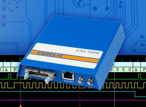
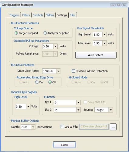
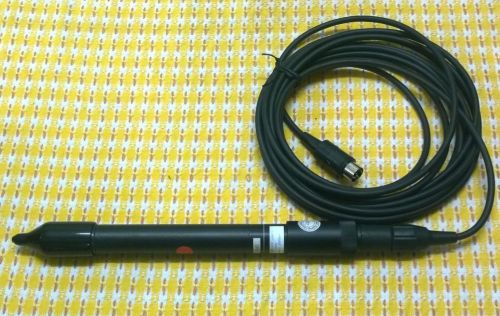
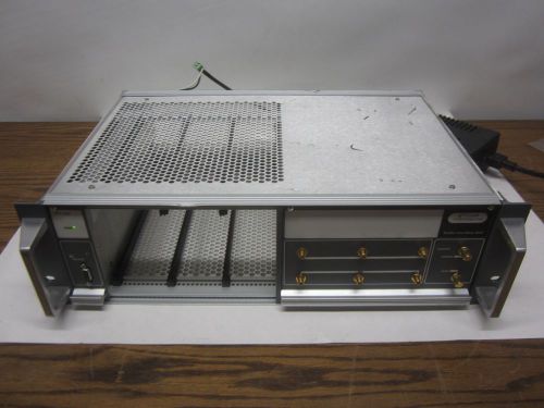
Brand | Corelis |
| MPN | 90002 | ||
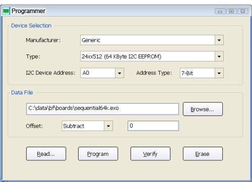
| Model | CAS-1000-I2C/E | ||
| Country/Region of Manufacture | United States |
Directions
Similar products from Other Equipment for Electrical Testing
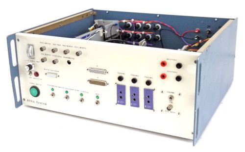
AERx System Therm Heater Motor Temperature Control Controller Power Unit PARTS
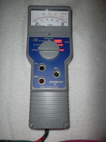
Tempo Textron - 1137-5002 - Sidekick T&N Test Set
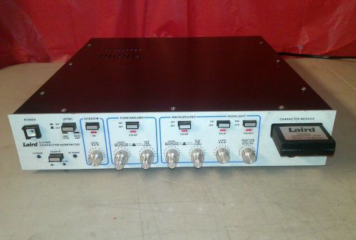
Laird Telemedia CG-7000ES Character Generator & Module CG7000
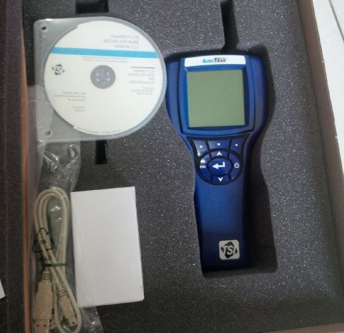
AeroTrak 9303 Handheld Airborne Particle Counter NEW
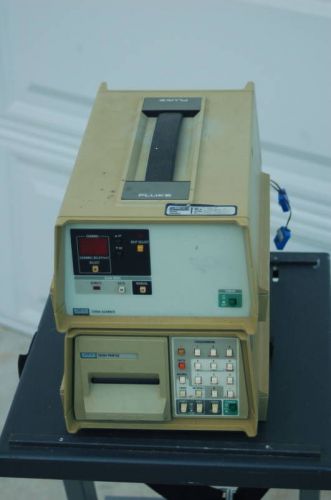
Fluke 2300A thermo Temperature Scanner + 2030A Printer
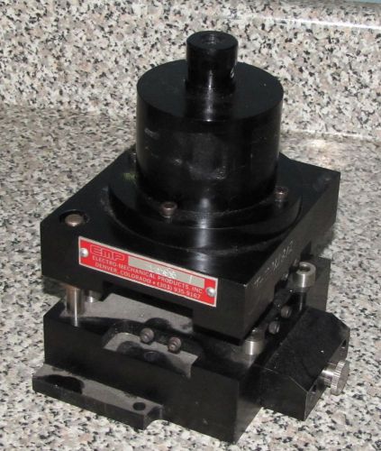
EMP ELECTRO-MECHANICAL PRODUCTS INC #1195 SMALL PRESS ??- f
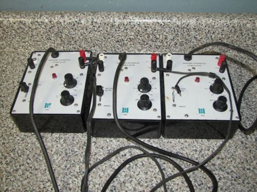
HARVARD APPARATUS STIMULATOR MODEL 343
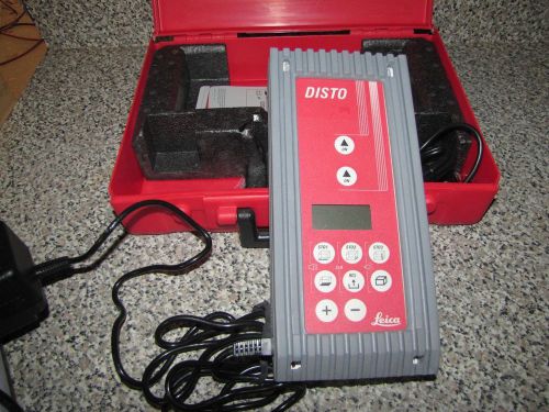
LEICA DISTO LASER DISTANCE METER
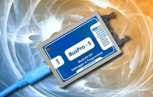
SPI Exerciser - BusPro-S by Corelis
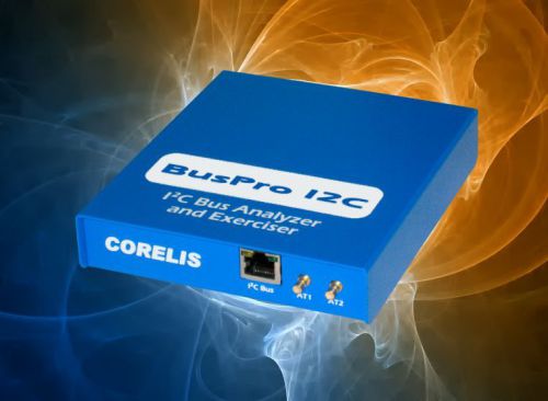
Bus Analyzer - Corelis BusPro-I
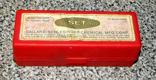
GALLARD PH-SET D10 DUOTEST PH INDICATOR PAPER
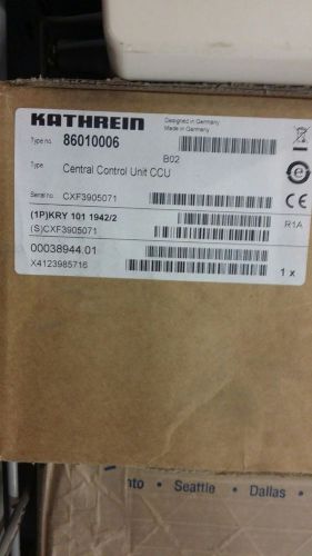
Kathrein Central Control Unit CCU 86010006
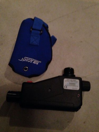
Noyes OFS 300-200C Optical Fiber Scope
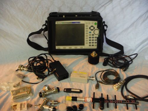
ANRITSU MT8222A BTS Master Base Station Analyzer - (041219)
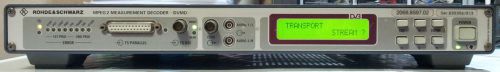
Rohde & Schwarz MPEG 2 MEASUREMENT DECODER DVMD DVB 2068.8597.02

Digital Monitor Car Volt Voltmeter LCD Cigarette Lighter Voltage Panel Meter
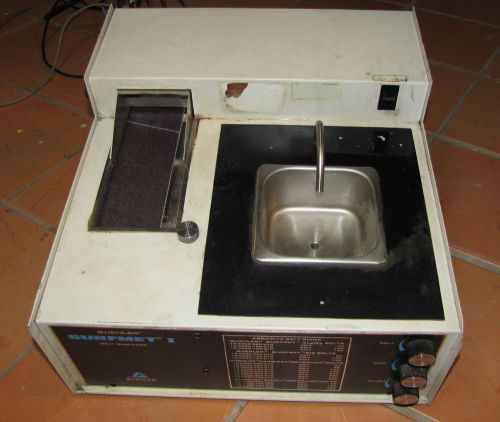
BUEHLER SURFMET I BELT SANDER SURFACER
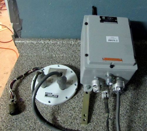
KILARK X-RAY J-BOX 12-104A-BAY DB-8106 W/ COHU 4864-5000 CONNECTOR
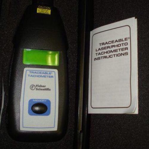
FISHER SCIENTIFIC TRACEABLE LASER TACHOMETER CAT. 05-028-24 (1 Qty)
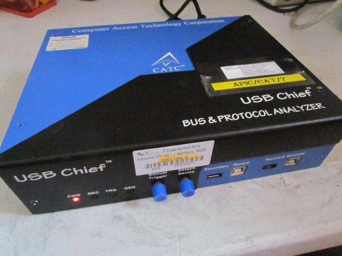
CATC USB Chief Bus & Protocal Analyzer LeCroy
People who viewed this item also vieved
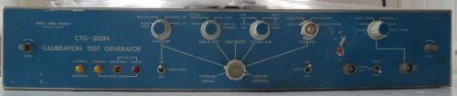
Leitch Video Limited CTG-210N Calibration Test Generator For Parts or Repair
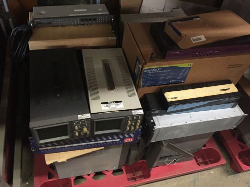
Bulk listing Sony, Textronix, etc. video/audio equipment.
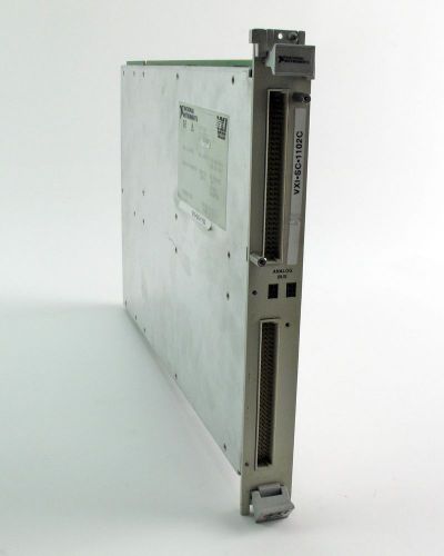
National Instruments NI VXI-SC-1000 Carrier w/ VXI-SC-1102C Amplifier Module
Testo 0635 1540 ,3 Function Probe Temp/RH/Velocity for 400 0635 1540 (#1184)
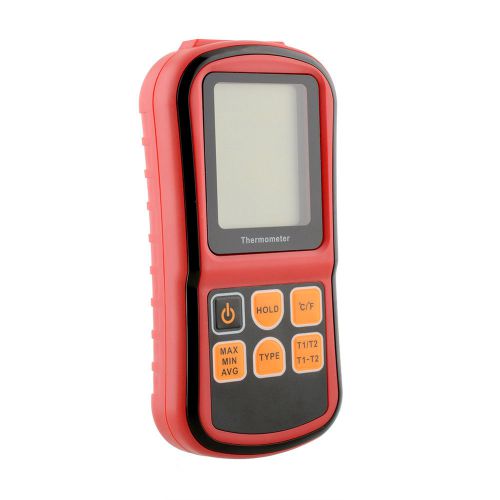
new Portable 2-Channel Thermocouple Thermometer detector meter -250~1767°C
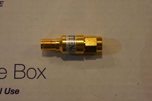
ATTEN-SMSF-6 SMA Andrew Commscope Attenuator
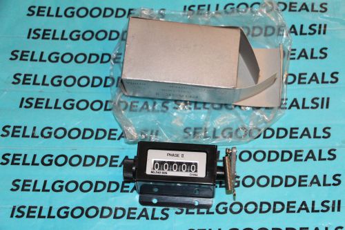
Phase II 340-005 Counter 5-Digit 340005 New
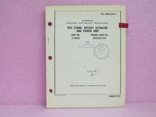
Military Manual LT-1044B Test Stand, Rot. Act. & Pwr. Unit OPR/SVC w/Sch. & IPB
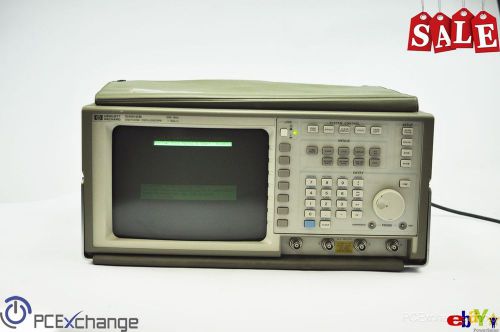
HP 54512B Digitizing Oscilloscope
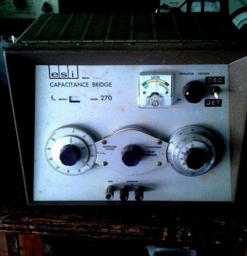
Vintage ESI Capacitance Bridge model 270
Accurate instruments co. Inc. New York model 151 with X. Reference book
Corning MobileAccess Radio Interface Unit, #2
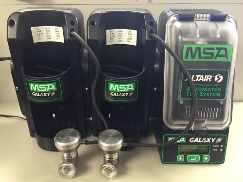
ONE MSA GALAXY ALTAIR "5" AUTOMATED TEST SYSTEM FOR GAS DETECTORS
GR General Radio 1556-A Impact Noise Analyzer
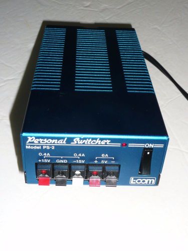
Personal Switcher L-Com model PS-2 Power Supply
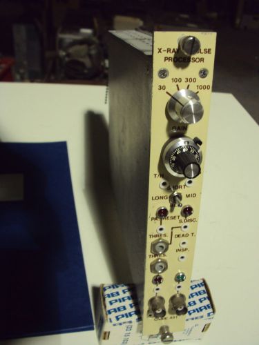
Cassie 401, X-ray Pulse Processor, nimbin nuclear plug-in
Keithley 7062 RF Switching Card
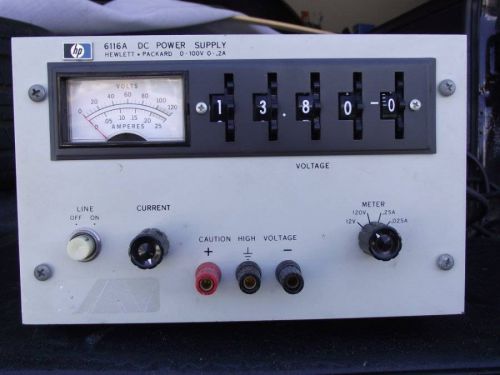
HP DC POWER SUPPLY 6116A 0-100V 0-.2A - PARTS/REPAIR
By clicking "Accept All Cookies", you agree to the storing of cookies on your device to enhance site navigation, analyze site usage, and assist in our marketing efforts.
Accept All Cookies