

US $99.99
Directions
Similar products from Engines
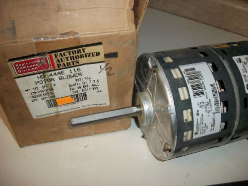
Carrier HD44AE116 Blower Motor
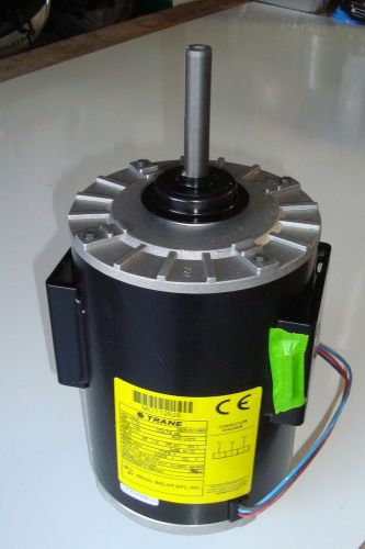
TRANE CONDENSER FAN MOTOR MOT12628, # P56C77A05, 1.5 HP, 460V 3 PHASE - NEW
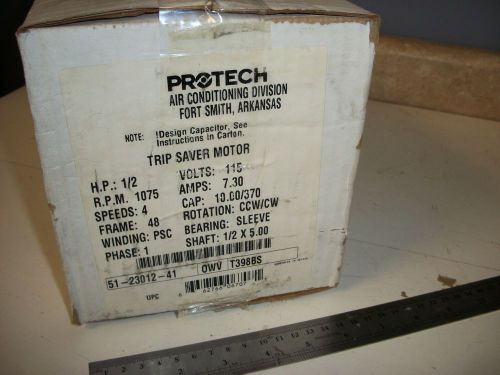
Rheem Ruud Protech Parts 51-23012-41 1/2 HP 115 Volt Furnace Blower Motor
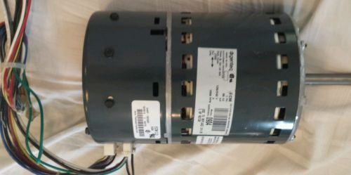
York Affinity series furnace blower motor
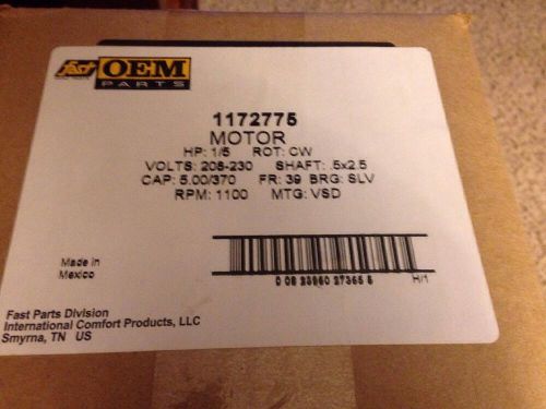
Fast Parts Motor 1172775. New In Box.
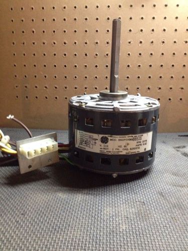
New GE 1/2 HP 1625 RPM BLOWER MOTOR 5KCP39PGB810S 230V
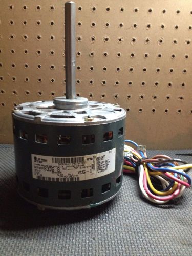
GE 1/3 HP Motor 5KCP39HG New 1075 RPM 230V

Trane Intellipak HVAC Condenser 1.25 HP Motor With Fan Blades 30" Dia / Warranty
Carrier FV4BNF002000AAAA EVAP COIL AND VARIABLE SPEED BLOWER MOTOR WITH BOARD
Carrier Bryant 5KCP39GGB851S GE Motor Blower Motor 1/4 HP 3SPD 115V HC41SE115
GE Motors 5KCP39GGS336S Blower Motor 1/3HP 1075RPM 1PH 115V 5.20A Carrier Bryant
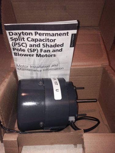
Dayton Motor 3M290D new in the box
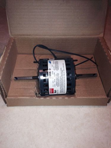
Dayton motor 3M083D new in box
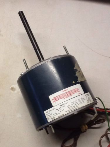
TRANE WW94X904 1/3 HP 208-230V,1075/750 RPM, Condenser Motor WW94X 904 ac
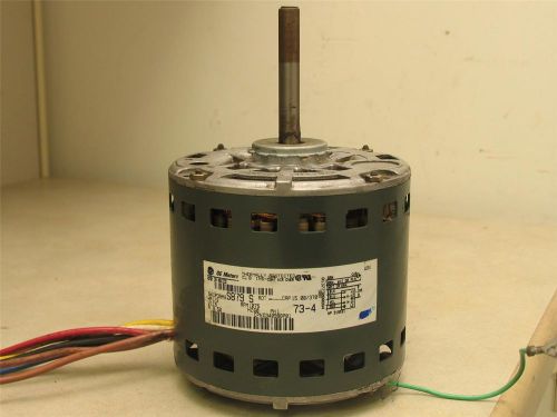
GE Motors 5KCP39MGS879S Blower Motor 1/2HP 115V 1075RPM 1PH 60Hz CPND340988P01
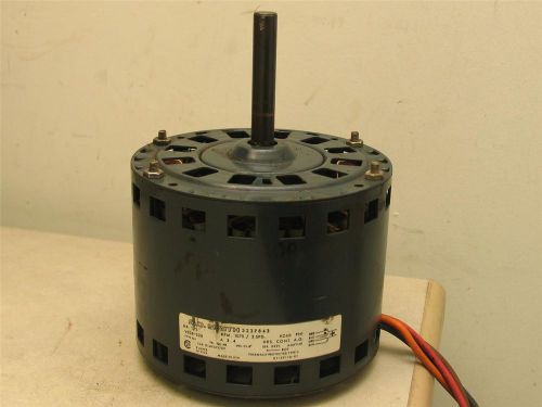
A.O. Smith 323P843 Blower Motor 1/2HP 1075RPM 2SPD 208/230V 1PH 60Hz
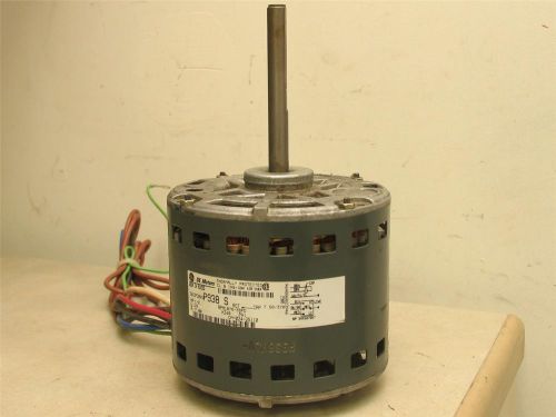
GE 5KCP39KGP938S Blower Motor 1/2HP 115V 1075RPM 3SPD 60Hz 1PH 7.00A
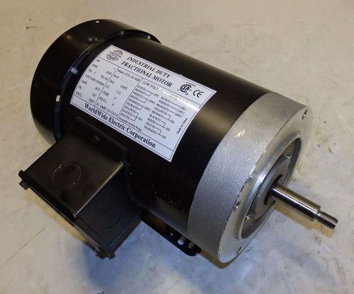
Worldwide Blower Motor ATJ1-36-56JB
Coleman Fasco Furnace Exhaust Inducer Motor 71215906 7121-5906
People who viewed this item also vieved
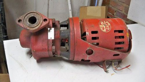
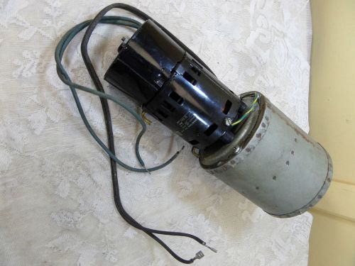
BELL & GOSSETT Circulating Pump & Motor 1/6hp Series 100 PR DP 102177 Parts
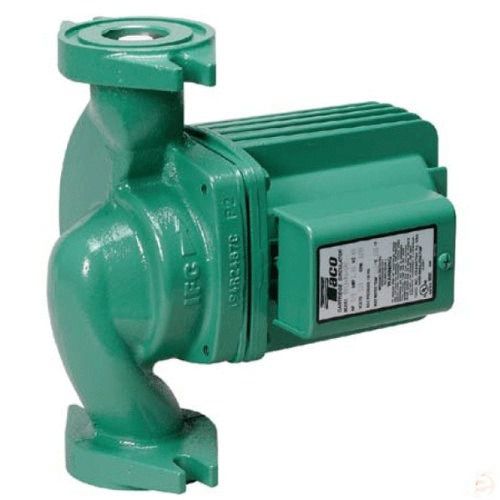
TACO 0012-F4-IFC CAST IRON CARTRIDGE CIRCULATOR PUMP WITH INTEGRAL FLOW CHECK
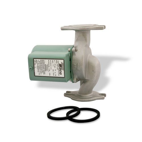
NEW TACO 007-SF5 STAINLESS STEEL CARTRIDGE CIRCULATOR PUMP, 1/25 HP
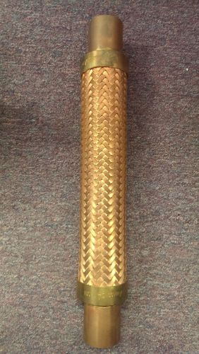
New Anaconda 2020F 2-1/8" OD Bronze Vibration Eliminator
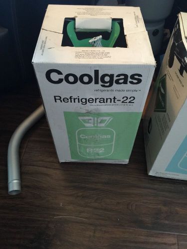
NEW Coolgas 30 Lb R22 Freon Tank Factory Sealed R-22 30#
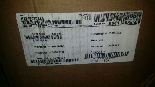
BRISTOL, YORK COMPRESSOR PART #: H22A503DBLA - COMPRESSOR H22A503DBLA
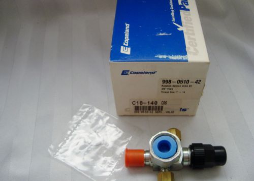
COPELAND 998-0510-42 ROTALOCK SERVICE VALVE KIT NIB 3/8" FLARE 1" THREAD
APISTE HEAT EXCHANGER - ENH 115L(R)-200
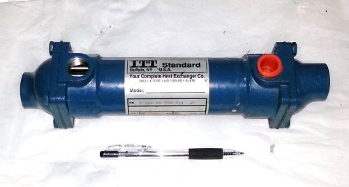
ITT STANDARD HEAT EXCHANGER SSCF PN: SN516002008001 Shell Tube Air Cooled Plate
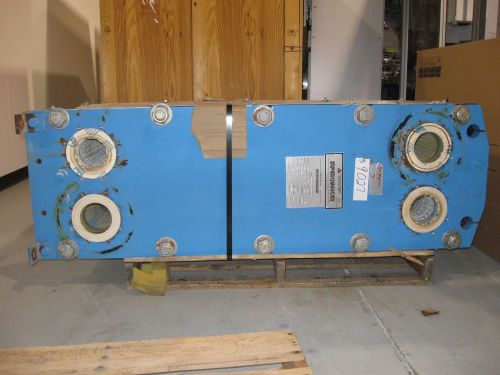
TRANTER SUPERCHARGER HEAT EXCHANGER 525.71 SQ. FT. GXD-042-H-5-UP-113
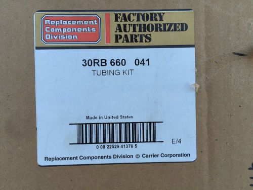
CARRIER AQUASNAP TUBING KIT 30RB660041 and TUBE ASSEMBLY 30RB660051
NEW!! HONEYWELL C7057A1000 CADMIUM SULFIDE SENSOR FOR CR7075
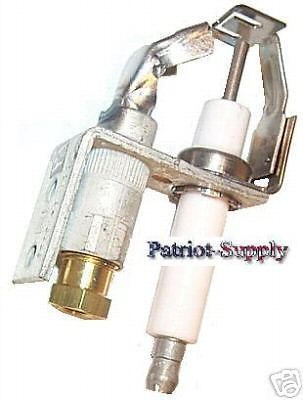
HONEYWELL Q345A1305 I.P. PILOT BURNER FOR NATURAL GAS
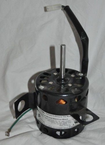
Packard 82121 Draft Inducer Blower Motor 115 Volts 3000 RPM 1.1A 60Hz 1/33HP CCW
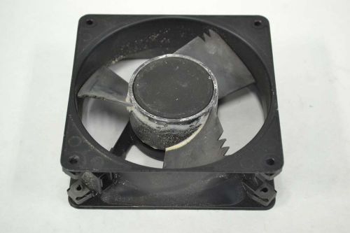
COMAIR ROTRON MX2B3 MUFFIN-XL 115V-AC 120MM 105CFM COOLING FAN B362521
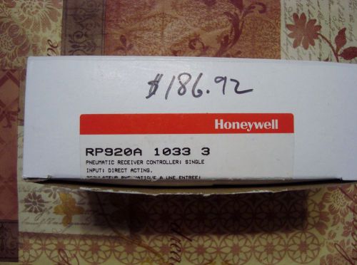
HONEYWELL PNEUMATIC RECEIVER CONTROLLER RP920A 1033 3 , NIB , 40 - 130 deg F.
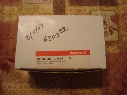
NEW IN THE BOX HONEYWELL PNUEMATIC RP920B 1031 3 RECIEVER CONTROLLER
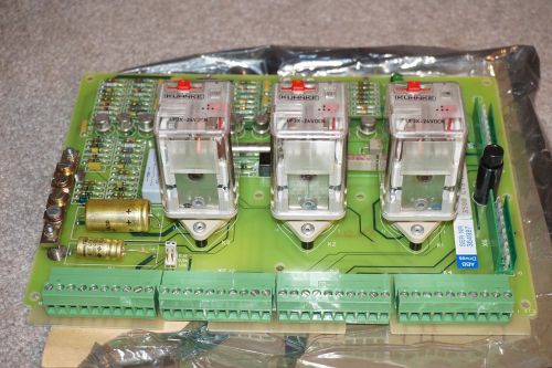
NEW ABB Stromberg 5761042-5k Drives Centrifugal Pump Control Board 3500-CTS
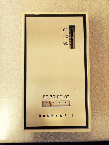
Honeywell T921A 1191 Thermostat
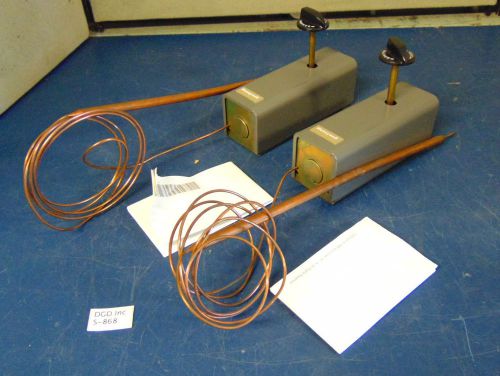
Lot of 2 Honeywell T6031E 1004 Unit Thermostat 3-Wire 250V "NEW IN BOX" S868
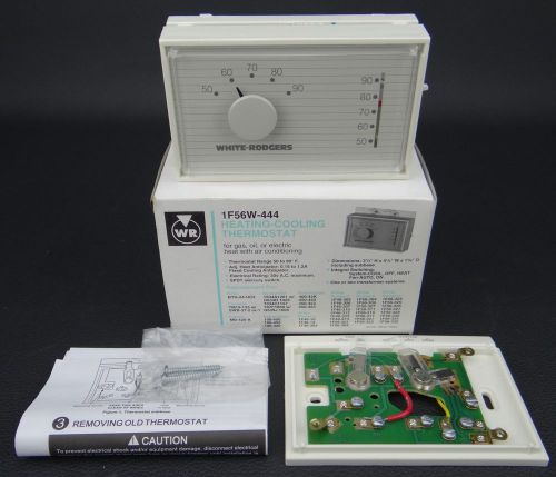
White Rodgers 1F56W-444 Heating Cooling Thermostat PN# 81-6080 WILMAR - NEW
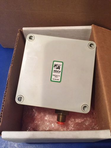
Kele, P100BTE-05 Pressure Transducer
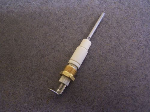
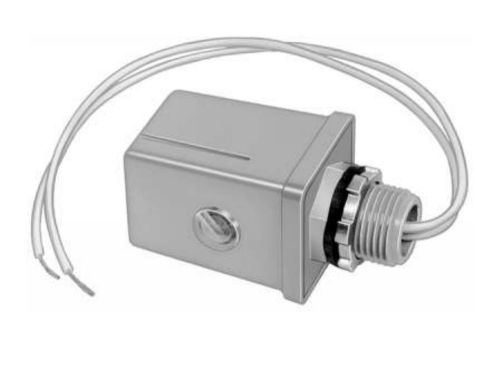
Baso Y75AS-1HJ Flame Sensor L38-662 W0637
Norton Model 201N Furnace Hot Surface Ignitor Igniter
By clicking "Accept All Cookies", you agree to the storing of cookies on your device to enhance site navigation, analyze site usage, and assist in our marketing efforts.
Accept All Cookies