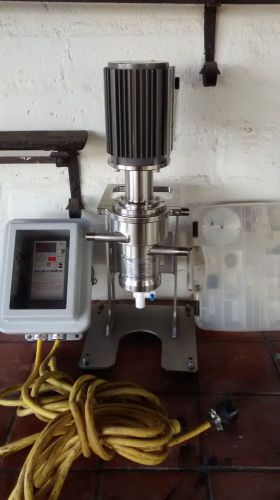
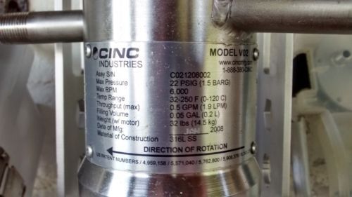
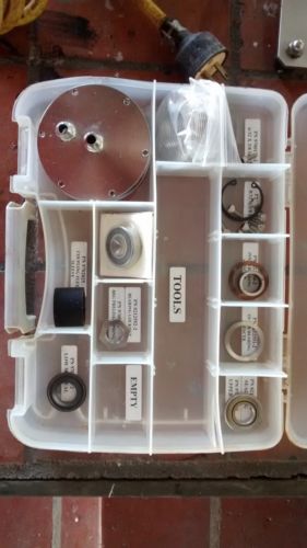
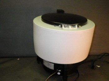
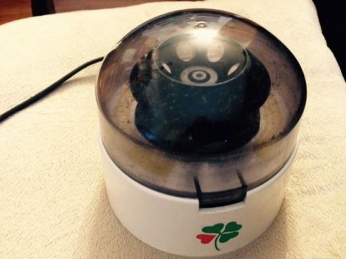
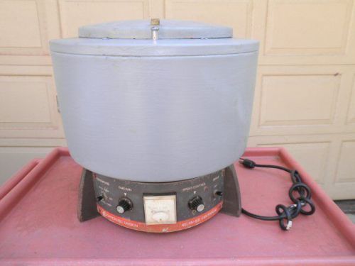
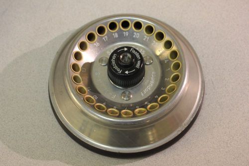
Excellent condition comes with everything as shown in photos. Let me know if you have any questions. Mix, react, and/or separate liquid-liquid mixtures in a single device Highly flexible design operates effectively under changing inlet concentrations, variable flow rates, and flow disruptions Heavy-duty SS componentry can be quickly cleaned and inspected (suitable for CIP and autoclavable) Interchangeable weirs allow for broad applications in research, pilot plant, or production operations Users find this design to be superior to most disk-stack style centrifuges, gravity-based decanters, coalescer and DAF type separators, mixer/settler systems, and extraction columns. It is suitable for separation of liquids with specific gravity differences of 0.05 or better and can process immiscible droplet sizes that are up to 10 im. Users may interchange weirs to accommodate for liquids of varying specific gravity and viscosity. A second inlet port allows the introduction (down to 20 mL/min) of mixing additives to the liquid for extraction, reaction and washing. What's Included: centrifugal chamber, 1/8-hp electric motor with variable speed controller, high- and low-mix bottom plates plus ten weirs (ranging 0.825" to 1.050" dia), and a CD-ROM including weir selection software, dynamic-image instruction package, and maintenance guide. Explosion-proof motors add a 50-ft power cable and a hazardous environment multipin connector. Specifications Wetted parts (rotor head and sleeve O-rings) PTFE-encapsulated Viton® Motor type Standard Refrigerated No Wetted parts (Housing) 316L stainless steel Power (VAC) 110 Fitting 3/8" NPT(M) Wetted parts (o-ring) PTFE Brand CINC Dimensions 9"W x 25"H x 9"D (22.8 cm x 63.5 cm x 22.8 cm) Product Type Centrifugal Separator Theory of Operation The CINC Liquid-Liquid Centrifugal Separator utilizes the force generated by rotating an object about a central axis. By spinning two fluids of different densities within a rotating container or rotor the heavier fluid is forced to the wall at the inside of the rotor while the lighter fluid is forced toward the center of the rotor. In the figure the mixed fluid is shown in green, the lighter phase fluid in yellow and the heavier phase fluid in blue. As can be seen the input fluids enter already mixed (separation process) or independently (extraction process) through one or both inlets. The fluids mix in the annulus between the rotor and the inside of the housing in the mixing zone. The fluids are then fed through an inlet or hole at the bottom of the rotor. A diverter plate or disk is used to direct the fluid to the inside of the rotor sleeve (shown in gray). As additional fluid is introduced to the rotor the fluid within the rotor is forced upward to the rotor underflows and weirs. The light phase fluid having a lower density flows toward the center of the rotor (shown in yellow) where it exits the rotor over the lighter phase weir through the lighter phase outlets. The heavy phase fluid continues up the rotor (shown in blue) through the underflows, then exits over the heavy phase weir. Each fluid is collected in its own collector ring and then leaves the separator through the heavy and light phase outlets. Theory of Separation The separation performance of the CINC separator is measured by the effluent quality of one or both of the output fluid phases. There are several parameters that need to be considered in optimizing the performance of the CINC unit for a specific process. These parameters include viscosity and density of the two liquid phases (at the process temperature), the input ratios, the total flow rate, and the rotor speed (RPM). How efficiently two fluids will separate in a centrifuge is best described by Stokes Law: where: Vc = the centrifugal settling velocity d = liquid droplet diameter rH = density of heavy phase rL = density of light phase r = radial distance of liquid from rotor axis w = angular velocity (RPM of rotor) havg = average viscosity of processed fluids The settling velocity, Vc , is an important parameter in phase separation, as it is a measure of how rapidly two immiscible phases will separate. From this equation, the parameters that will result in the most efficient phase separation (largest Vc) can be evaluated. Parameters that would increase Vc include: larger droplet size, increasing the density difference between two phases, high RPM, and low viscosity. The converse is also true - less efficient phase separation is observed in systems with: smaller droplet size, small density differences, low RPM, and viscous fluids. One parameter that the operator can readily control when optimizing the CINC equipment is the RPM. Another is fluid residence time while in the rotor, which is directly controlled by feed rate. Lowering the feed rate can improve the quality of both separated phases by allowing more time to achieve efficient separation. Because the CINC separator was originally designed to operate as a contactor, fluids are premixed in the annulus between the housing and the spinning rotor. Although higher RPM’s (w) result in more g-forces inside the rotor, they also result in more mixing in the annulus, and therefore smaller droplet size (d). As a result of this, an increase in RPM’s will sometimes result in no improvement to separation efficiency (Vc does not increase), as the increased angular momentum (w) is being offset by a decreasing droplet size (d). Therefore, if better phase separation is needed, increasing the rotor speed will sometimes be of benefit (greater g-forces generated), but sometimes not (smaller droplet size). This must be determined for each set of application conditions and the fluids processed. In the figure the mixed fluid is shown in green, the lighter phase fluid in yellow and the heavier phase fluid in blue. As can be seen the input fluids enter already mixed (separation process) or independently (extraction process) through one or both inlets. The fluids mix in the annulus between the rotor and the inside of the housing in the mixing zone. The fluids are then fed through an inlet or hole at the bottom of the rotor. A diverter plate or disk is used to direct the fluid to the inside of the rotor sleeve (shown in gray). As additional fluid is introduced to the rotor the fluid within the rotor is forced upward to the rotor underflows and weirs. The light phase fluid having a lower density flows toward the center of the rotor (shown in yellow) where it exits the rotor over the lighter phase weir through the lighter phase outlets. The heavy phase fluid continues up the rotor (shown in blue) through the underflows, then exits over the heavy phase weir. Each fluid is collected in its own collector ring and then leaves the separator through the heavy and light phase outlets. To improve separation for shear sensitive fluids, or in applications where pre-mixing is of no benefit, CINC has developed a low-mixing option that minimizes mixing in the annulus. This option, referred to as the low-mixing sleeve, allows operation at higher RPM’s with minimal increase in mixing. The low mixing sleeve is recommended for applications where separation is the most important (e.g. oil/water separation, phases already premixed, shear sensitive fluids).
By clicking "Accept All Cookies", you agree to the storing of cookies on your device to enhance site navigation, analyze site usage, and assist in our marketing efforts.