US $55.00
| Condition: |
New: A brand-new, unused, unopened, undamaged item in its original packaging (where packaging is
applicable). Packaging should be the same as what is found in a retail store, unless the item is handmade or was packaged by the manufacturer in non-retail packaging, such as an unprinted box or plastic bag. See the seller's listing for full details.
...
|
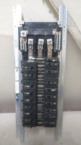
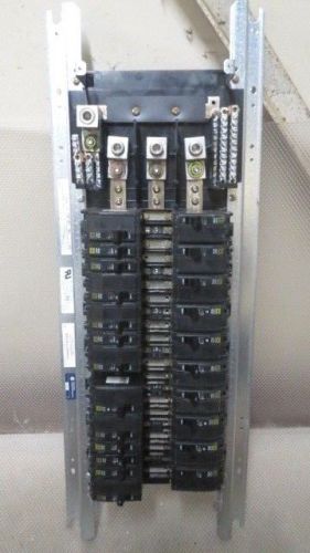
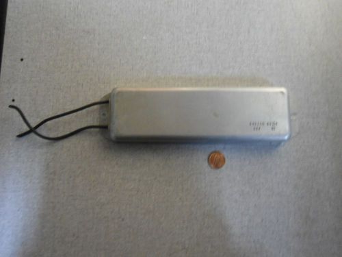
Brand | WINDOWS |
| Country/Region of Manufacture | United States | ||
| Model | EXCEL |
Directions
Similar products from Electrical breadboards
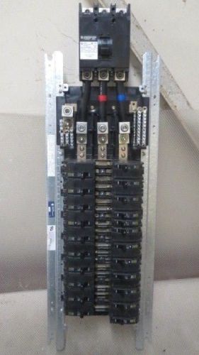
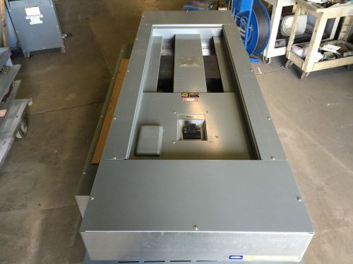
SQUARE D 42 CIRCUIT INTERIOR PANEL W/ 225 AMP MAIN + BREAKERS MODEL NQOM442L225
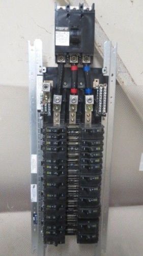
SQUARE D 42 CIRCUIT INTERIOR PANEL W/ 225 AMP MAIN + BREAKERS MODEL NQOM442L225
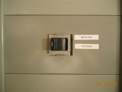
Pacific Electric (D446) 600 A Main Breaker Panelboard Section Used w/new breaker
SQUARE D 42 CIRCUIT INTERIOR PANEL WITH ASSORTED BREAKERS MODEL: NQOM442L225
Square D NQOD Main Lug/Circuit Breaker Panel Board 225 Amp 3 Phase in Enclosure
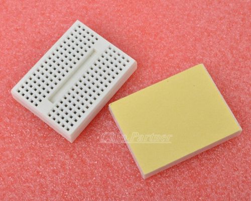
1PCS White Solderless Prototype Breadboard 170 Tie-points for Arduino
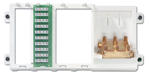
NEW Leviton 010-47606-BTV Basic Telephone and Video Unit
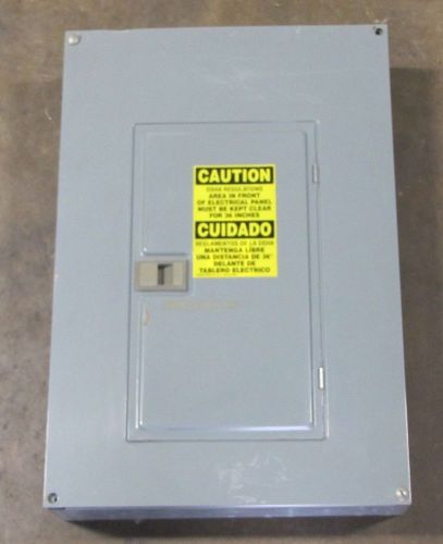
SQUARE D QOC24U QO LOAD CENTER SERIES G1 ELECTRICAL BREAKER PANELBOARD CABINET
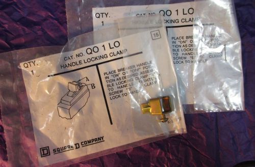
SQUARE D HANDLE LOCKING CLAMP QO 1 LO K218025 QO1LO CIRCUIT BREAKER PANEL LOCK
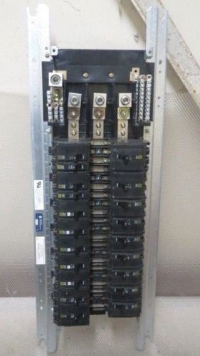
SQUARE D 42 CIRCUIT INTERIOR PANEL WITH ASSORTED BREAKERS MODEL: NQOM442L225
SQUARE D 42 CIRCUIT INTERIOR PANEL WITH ASSORTED BREAKERS MODEL: NQOM442L225
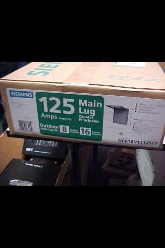
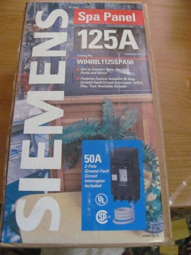
LOT OF 5- NEW.SIEMENS W0816ML1125CU 125AMP OUTDOOR MAIN LUG BREAKER PANEL BP-105
SQUARE D I-LINE HCP PANELBOARD MLO 400 AMP 480Y/277V 3P 4W HC4268DB HCW68TSD
SQUARE D 42 CIRCUIT INTERIOR PANEL WITH ASSORTED BREAKERS MODEL: NQOM442L225
SQUARE D I-LINE PANELBOARD MCB 800 AMP 480Y/277V 3P 4W HCM MAP36800 HC3291B
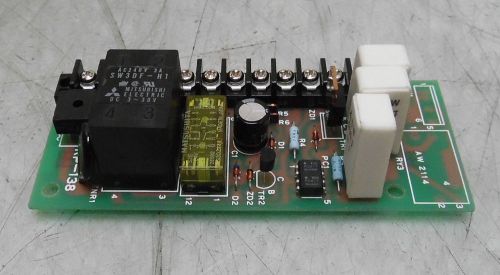
Static Controls Power Supply PC Board, # RP-138, 55A0006 A, Used, WARRANTY
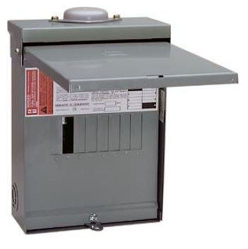
Square D Main Lug 120/240V 100A QO612L100RB Outdoor Load center
People who viewed this item also vieved
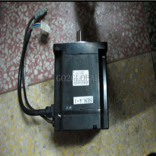
1PC Yaskawa SGMPH-15AAA41 servo motor 60 days warranty
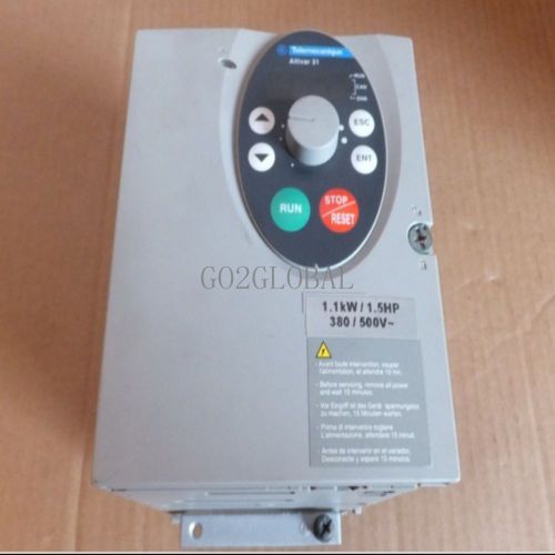
1PC Schneider ATV31HU11N4A 1.1KW inverter, 1PC 60 days warranty
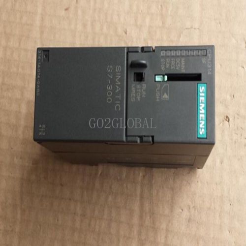
CPU314 1PC 6ES7 314-1AG14-0AB0 60 days warranty
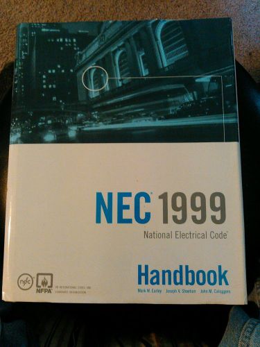
NATIONAL ELECTRICAL CODE NEC HANDBOOK MANUAL 1999 WITH DUST JACKET
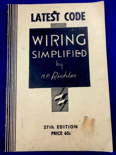
Rare 1962 Latest Code Wiring Simplified by H.P.Richter 27 Edition Book
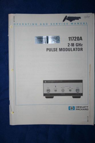
HP11720A 2-18 GHZ PULSE MODULATOR Operating and Service Manual WITH SCHEMATICS
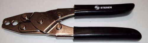
Steren 204-011 Crimping Tool RG 59/62 2 Cavity Hex Crimp 8"

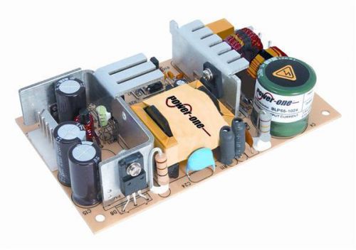
Bel Power Solutions BLP55-3300 AC/DC Power Supply
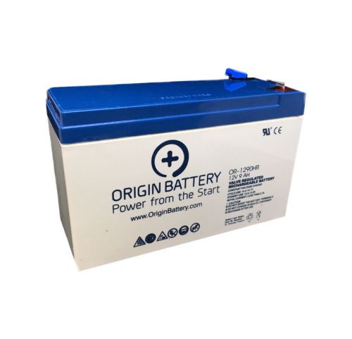
APC BE750G Battery Replacement
Cooper B-Line Screw Cover 6"x6"x4" Electrical Enclosure Junction Box 664 SC
Electric Meter Box - Gray & New
Bud Industries NEMA Die Cast Aluminum Box, With EMI/RFI Shielding ANS-3809

3M OPTIME 105 EARMUFF H10P3E NIB
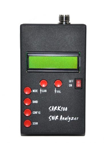
SARK100 1 - 60 Mhz ANT SWR Antenna Analyzer Meter Tester For Ham Radio Hobbists
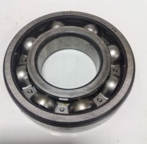
SKF SINGLE ROW BALL BEARING 6317/S1
By clicking "Accept All Cookies", you agree to the storing of cookies on your device to enhance site navigation, analyze site usage, and assist in our marketing efforts.
Accept All Cookies