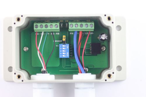
How to contact us? cell me:+86 0552 2871515 +86 13695559100 QICQ:1303409997 Wechat:916215381 EMAIL:1303409997@qq.com weighing modules specifications Chapter 1 technical specification 1.1 general technical specifications Power supply: DC 9 ~ 28 VDC power consumption: < 1 w working current: according to the number of external sensors and power supply voltage Applicable environment: temperature: - 40 ~ 85 humidity: 10% ~ 95% (no lon) Protection grade: IP65 installation: installation holes are fixed Weight: 0.25 kg of material 1.2Analog part applicable sensor types: suitable for all resistive load and strain type weighing transducer excitation voltage sensor: 5 VDC plus or minus 3%, the maximum current of 100 ma input signal range: plus or minus 11 mv temperature coefficient: (reading of 0.001% + 0.3 d) or less / nonlinear error: 0.003% or less f.s. Internal resolution: 1/16777215 stable display resolution: 1/10000 sampling rate: 12 times / 50 times configurable sampling method: Sigma Delta 1.3 communication section Communication mode: RS485 Communication protocol: MODBUS RTU Communications parameters: 9600,8,n,1 Electrical isolation: 1000VDC Supported baud rate: 2400, 4800, 9600, 19200, 38400 1.4 device capabilities Calibration mode: digital, all operations can be done through the RS485 bus power on reset to zero: 0~65535 Dynamic chasing zero: 0~65535 Fast calibration:yes Peel range: 0~65535 Manual peeling:yes Chapter 2 technical specifications 2.1 installation This transmitter belongs to precision electronic instruments, installation, connection and operation should be very careful. l Although the product meets industrial temperature range, but in order to ensure the accuracy of the transmitter, please try to avoid to install transmitters in direct sunlight or sudden changes in temperature of the environment. l Ensure that the transmitter has enough room for air cooling l Transmitter only protection normal splash of water, is not used in the immersion environment l Please avoid the transmitter's violent vibration and impact l Do not use in any hazardous place to install the transmitter. 2.2 Power supply l Power supply: 9 ~ 28VDC, sufficient capacity, non-transient, clutter l May form condensation inside the transmitter, we recommend always transmitter power, or open check condenser on a regular basis l Use an appropriate power cord, confirm power cord is rated for voltage or current to meet the requirements, if not enough may cause leakage or fire l Special attention at the time of multi-machine power, please answer as follows the power cable 2.3 interface connections 2.4 sensor connection l The transmitter applies all of resistor strain type sensor l Sensor output signal is very weak, please try to shorten the length of signal cables, prohibition of signal wires and power lines were tied together, otherwise the transmitter interference is likely to affect the accuracy of measurement. l Sensor's cable cannot be cut l Tidy up the line in front of the calibration of the sensor and can no longer be calibrated come back in, otherwise it will result in measurement errors l Sensors connected to the terminal block must be reliable, beating poor contact will result in data are not allowed. l Note: Please do not use the instrument excitation as it, as it may cause the meter to beat or weighing the value not even burn module!! 2.6 the RS485 interface One-to-one Note: 1) RS485 interface does not have a fixed standard, depending on the manufacturer pin order, and discipline may not be the same, users can check out related products RS485 pin map. 2) of each instrument must be hand in hand, no connection can be a star or cross, if there is a star join or fork, interference is very large, and will result in poor communication, not even communication. 3) communication cable preferably shielded twisted-pair cable (shield grounding), then twisted, do not use ordinary cable, if you use ordinary cable, interference will be very large, poor communications, not even communication. Communication cable length must not exceed 1200 m. 4) if necessary, please access terminal resistor, to enhance the immunity system, termination resistor inside has been contained, just plug in the "termination resistor skip Cap." 5) Standard Edition up to 32 units can be connected modules, if you need a large network can be customized. 6) communication cable terminals must be connected securely, there should be no loose, otherwise, may burn out the module. 2.7 code switch definition 1 2 3 4 5 adress 1 2 3 4 5 ad OFF OFF OFF OFF OFF 1 OFF OFF OFF OFF ON 16 ON OFF OFF OFF OFF 2 ON OFF OFF OFF ON 18 OFF ON OFF OFF OFF 3 OFF ON OFF OFF ON 19 ON ON OFF OFF OFF 4 ON ON OFF OFF ON 20 OFF OFF ON OFF OFF 5 OFF OFF ON OFF ON 21 ON OFF ON OFF OFF 6 ON OFF ON OFF ON 22 OFF ON ON OFF OFF 7 OFF ON ON OFF ON 23 ON ON ON OFF OFF 8 ON ON ON OFF ON 24 OFF OFF OFF ON OFF 9 OFF OFF OFF ON ON 25 ON OFF OFF ON OFF 10 ON OFF OFF ON ON 26 OFF ON OFF ON OFF 11 OFF ON OFF ON ON 27 ON ON OFF ON OFF 12 ON ON OFF ON ON 28 OFF OFF ON ON OFF 13 OFF OFF ON ON ON 29 ON OFF ON ON OFF 14 ON OFF ON ON ON 30 OFF ON ON ON OFF 15 OFF ON ON ON ON 31 ON ON ON ON OFF 16 ON ON ON ON ON 32 Chapter 3 communication protocol 3.1 the MODBUS RTU communication protocol When the user uses the MODBUS RTU Protocol, RS485 serial hardware, serial communication parameters need to be set: address, baud rate, data bits, parity and stop bits (the default communications parameters: 9600,8,n,1). MODBUS function address is shown in the following table: all addresses are to keep the register offset, or 4000; Register description MODBUS Protocol, please refer to: SX-TJ11 register details 3.2 instructions for example Read the current weight value: 01 03 00 00 00 02 C4 0B Analysis: 01: the module address 03: read the holding register 00 00: begins reading from a maintained register 0 address 00 02: read 2 register values C4 0B:CRC16 checksum Read the current mass-reversion: 01 03 04 04 D2 00 00 5B 3A Analysis: 01: the module address 03: reply read holding registers 04: the valid data length of 4 bytes 04 D2: the value of the first register 00: 00: second register values 5 b 3A:CRC16 checksum Data is parsed 16-weight value of 00 00 04 D2, into 10 binary value: 1234. Other read or generated user configuration directives can be generated based on the Modbus-RTU instruction format. 3.3 calibration process overview If using a PLC or other PC to calibrate the module processes, you can follow the procedure below. ensure prior to calibration sensor and module have been fixed properly. remove the load on the sensor, keep the sensor weight is expected value of 0 the weight-bearing. constantly reads a current AD value, stable stability value when the value is written to the "zero-point calibration register AD value" to it. sensor load recommended load weight of not less than half of the greatest range. continuously reads the current AD, when stabilized the value written to stable value "AD full value calibration value register", And corresponding weight values to be written to at this time "full value calibration weight value". According to actual needs to adjust filtering parameters, dynamic, power on reset zero zero and other parameters.
By clicking "Accept All Cookies", you agree to the storing of cookies on your device to enhance site navigation, analyze site usage, and assist in our marketing efforts.