US $599.99
| “The unit passes all of the self tests and is guaranteed to work.” |
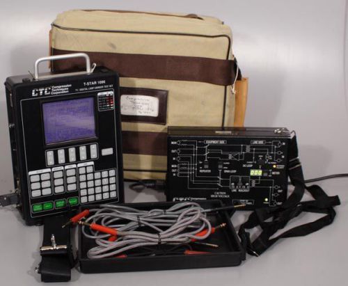
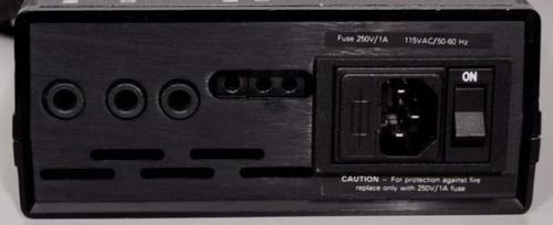
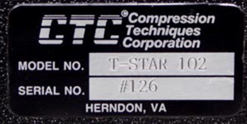
| Brand | Compression Techniques |
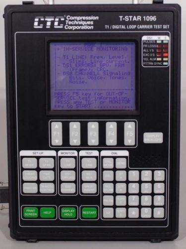
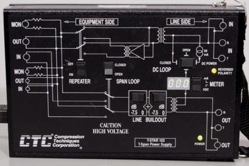
| Model | T-STAR 1096A w/102 |
Directions
Similar products from Other Measurement Tools for Telecom
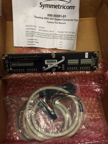
SYMMETRICOM TELECOM SOLUTIONS 090-55591-01 TIMEHUB 5500 DS1 CONN D0TPR00AAA
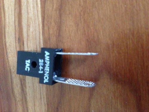
Amphenol 284-1 - Test Apparatus Connector TAC test adapter
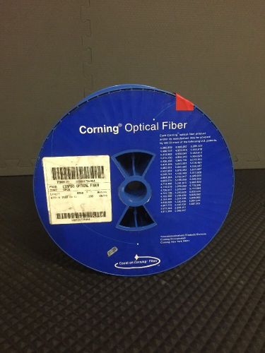
Corning Leaf(R) Optical Bare Fiber - Used Spool - CPC6 Coating - Attn 1550nm
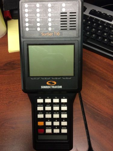
SUNRISE TELECOM SUNSET T10 SS150 TESTER
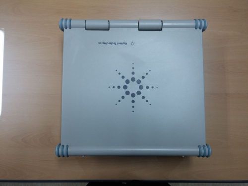
Agilent, Protocol analyzer, Second hand , J6800A
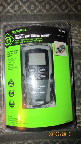
GREENLEE NETcat Micro Digital VDV Wiring Tester
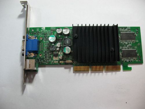
Dell-nVIDIA 64MB S-Video out Video Card TW-09P301 P73
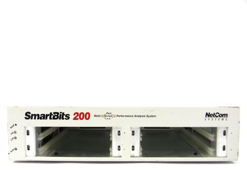
Spirent/TAS/Netcom SMB200 4-Module SmartBits Chassis 30 Day Warranty
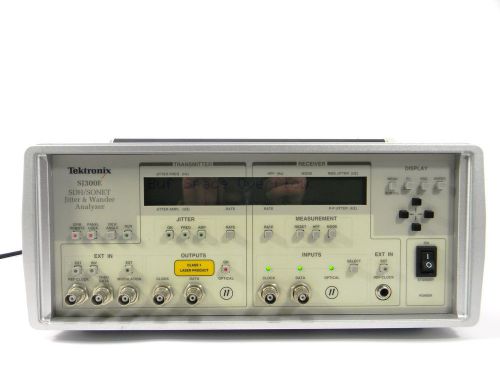
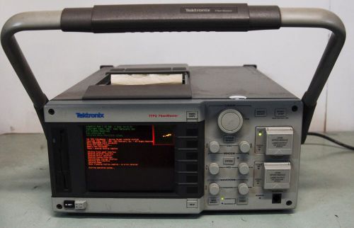
Tektronix SJ300E Analyzer 30 Day Warranty
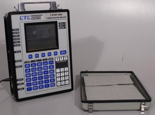
CTC T-STAR 1000 T1/Digital T-Carrier Analyzer Loop Carrier Test Set/Simulator
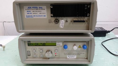
JDS RM3750B Z001 BACKREFLECTION/POWER METER 1625/1550 nm DUAL SOURCE
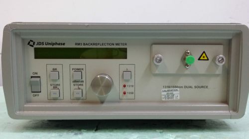
JDS RM3 BACKREFLECTION METER 1310/1550 nm DUAL SOURCE
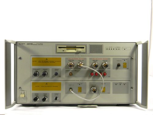
Agilent 70843B 12 Gbit/s Error Performance Analyzer 30 Day Warranty
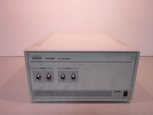
Spirent TAS5200 RF Converter Powers Up, 100-240VAC, 50-60Hz, 250W MAX, 10 AMP
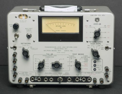
Wiltron 9041 Transmission Level and Return Loss Measuring Set

10 Ea == NEW == Telrad AdvanceIP - NEW - Avanti 3025 PHONE - MPN 79-611-1000/B
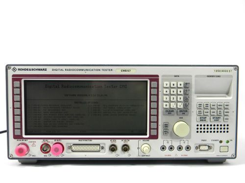
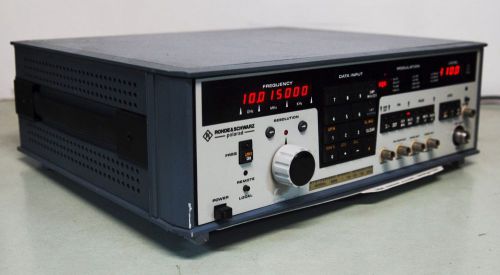
Rohde & Schwarz CMD57 Digital Radio Communication Tester - 30 Day Warranty
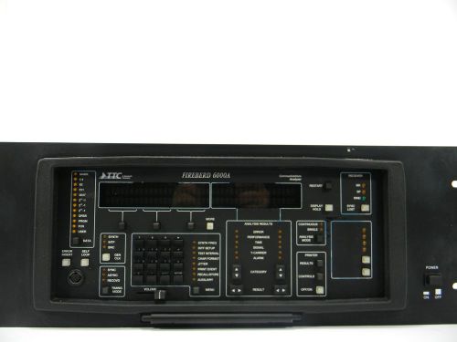
Acterna/TTC/JDSU/WG 6000A Communications Analyzer 30 Day Warranty
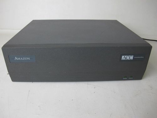
Newbridge Advanced Computer Communications Amazon Bridge/Router 8600439
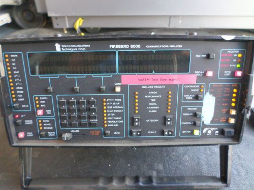
TELECOMMUNICATION TECHNIQUES FIREBERD 6000 W/TTC 43440 (DS1/DS3 ATM INTERFACE)
People who viewed this item also vieved
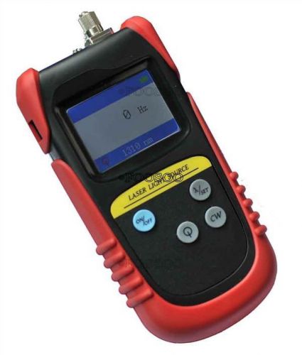
New TLD7002A Hand Held Optical Laser Light Source Dual Wavelength 850&1300nm
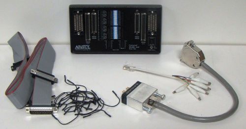
ADVICE Advanced IC Engineering Universal Modify & Test Set LAN WAN
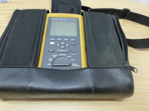
Fluke Lan Digital Cable Meter DSP100
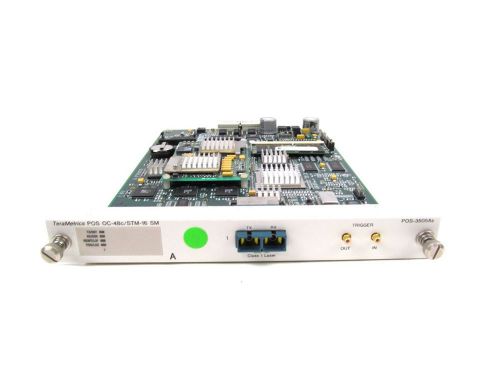
Spirent SmartBits POS-3505As ATM OC48 TeraMetrics POS OC-48c/STM-16 SM
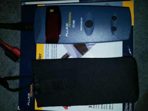
FLUKE NETWORKS TS100 CABLE LENGTH FAULT TESTER METER TDR Metric
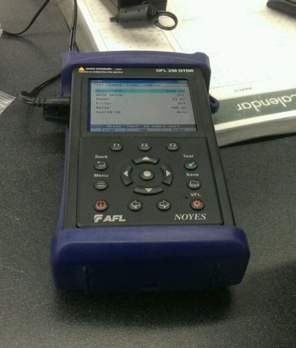
AFL Noyes OFL 250 Fiber Optic OTDR SingleMode 1310nm/1550nm SM VFL Power Meter
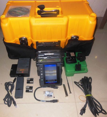
Fujikura FSM 70R Ribbon Splicer in excellent condition
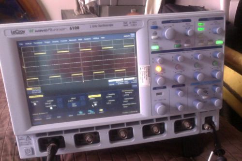
Lecroy 6100 1GHZ WaveRunner oscilloscope, 10 GS/s, light weight
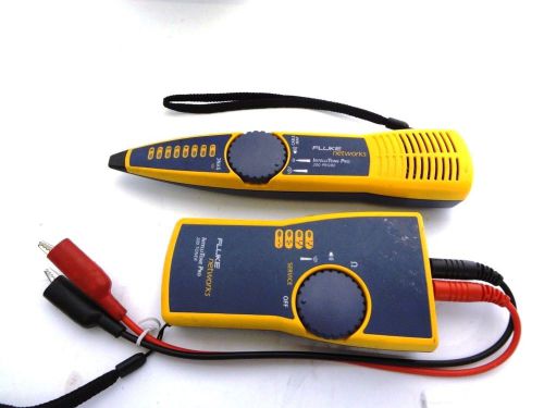
Fluke Networks IntelliTone Pro 200 Toner & IntelliTone Pro 200 Probe
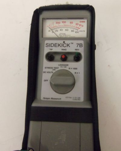
Tempo Sidekick 7B Telephone Tester
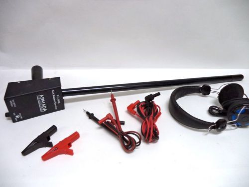
Armada Technologies Pro 700R Tech Tracker Wire and Valve Locator
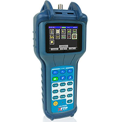
Lot of 4 trilithic model 3 plus colour screen new
HARRIS FLUKE TS44 DATA SAFE BUTT SET WITH CO CORD AND ABN LEADS
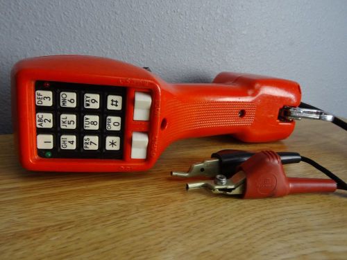
Harris Dracon TS21 Test Set Bell South Phone Tester Retro Vitage Red
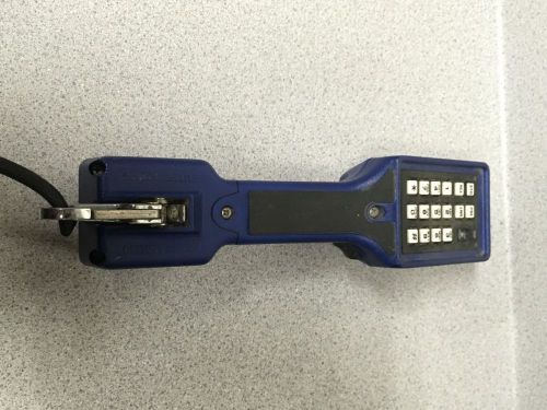
HARRIS DRACON TS22DS-009 TELEPHONE LINEMAN TEST/BUTT SET
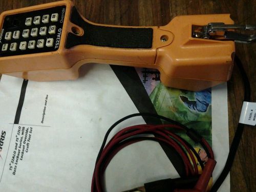
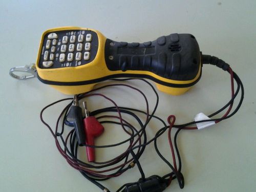
HARRIS FLUKE TS 22ALO DATA SAFE WITH ALERT & OVERRIDE WITH 2 WAY SPEAKERPHONE
Rode & Schwarz Polarad 309 Signal Generator
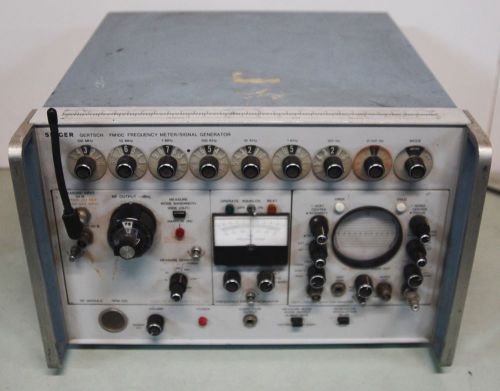
Singer Gertsch FM10C Frequency Meter Signal Generator
By clicking "Accept All Cookies", you agree to the storing of cookies on your device to enhance site navigation, analyze site usage, and assist in our marketing efforts.
Accept All Cookies