


US $2,250.00
| Condition: |
Used: An item that has been used previously. The item may have some signs of cosmetic wear, but is fully
operational and functions as intended. This item may be a floor model or store return that has been used. See the seller’s listing for full details and description of any imperfections.
...
|
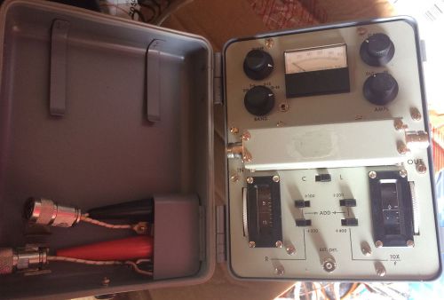
Brand | Delta Electronics INC |
| Country/Region of Manufacture | United States | ||
| Model | OIB-2 |
Directions
Similar products from Broadcast Monitors & Modulation Meters
Anritsu OSL Precision Calibration Kit DC-4.0GHz P/N 2000-768-R
Anritsu OSL Precision Calibration Kit DC-4.0GHz P/N 2000-767-R
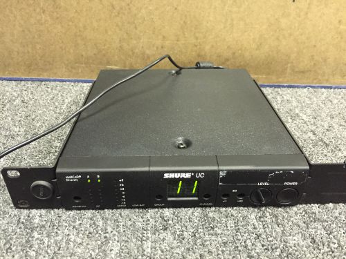
SHURE UC4-UA WIRELESS MICROPHONE RECEIVER 782-806 MHz
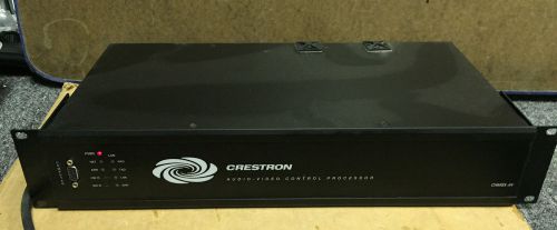
Crestron CNMSX-AV control processor
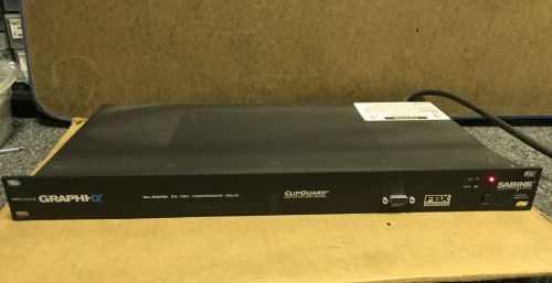
Sabine Graphi-Q All Digital Equalizer EQ FBX Compressor Delay GRQ-3101
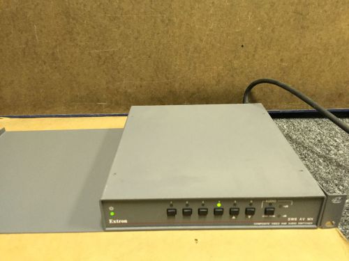
Extron Electronics SW6 AV MX VIDEO / AUDIO Switcher
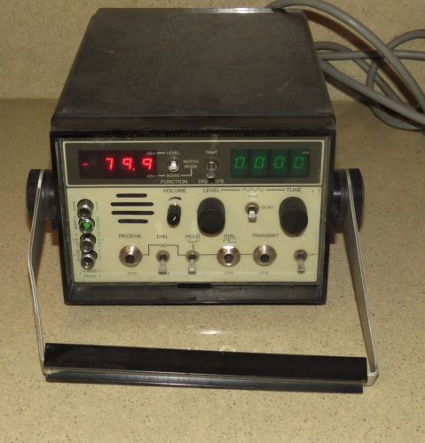
HALCYON Model 701A TRANSMISSION TEST SET -b
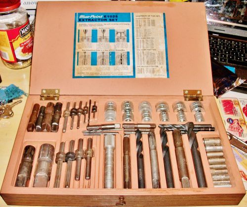
(Snap On) Blue Point e1025 extractor set wood box, Set + Extra. U.S.A.
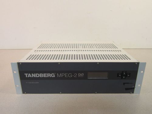
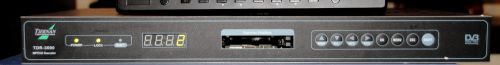
Tandberg TT1100 MPEG2-DVB Professional Decoder, Powers On, Nice Find, More Specs
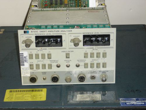
HP Agilent 8755C Swept Amplitude Analyzer Use In 180 Series Mainframes
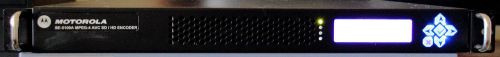
DVB/ASI/IP HD/SD MPEG-4/H.264 ENCODER MOTOROLA SE-5100 HD-SDI/SDI/ASI/IP INPUT
DVB/ASI/IP TS RE/MULTIPLEXER IP STREAMER MPEG2/4 TERAYON DM-6400 #3
DVB/DSNG/IPTV HD/SD MPEG-4/H.264 ENCODER TANDBERG EN8090 ASI/IP OUTPUT
DVB/DSNG MPEG-2/4 L-BAND UPCONVERTER SATELLITE SYSTEMS 950-1450 MHZ OUTPUT
MARSHALL BROADCAST VS-100 MPEG-4/H.264 ENCODER
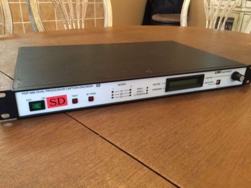
PDP-886 Closed Caption Encoder SD-SDI
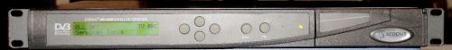
DVB-S MPEG-2 PROFESSIONAL RECEIVER SCOPUS IRD-2600 NO RESERVE
DVB-S MPEG-2 PROFESSIONAL RECEIVER SCOPUS/NDS SATCOM IRD-2600 NO RESERVE
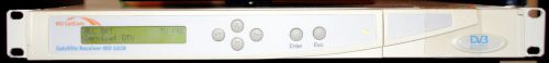
DVB-S MPEG-2 PROFESSIONAL RECEIVER TIERNAN TDR-3000 NO RESERVE
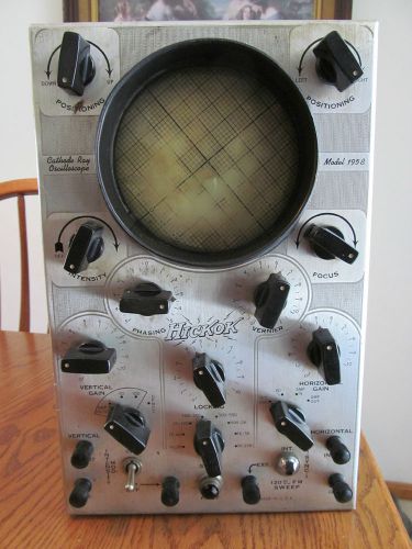
Vintage Rare 1940's Hickok Model 195B Cathode Ray Oscilloscope
People who viewed this item also vieved
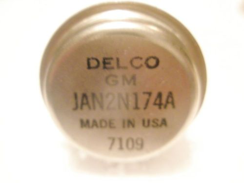
(NOS) DELCO/GM (USA) JAN2N174A POWER TRANSISTOR GERMANIUM TO-36 HOUSING
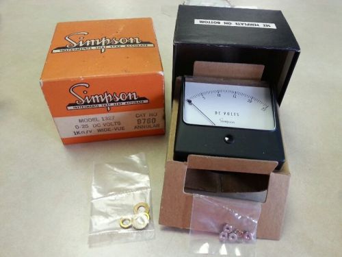
Simpson Model 1327, 0-25 VDC Panel Meter Cat #9760
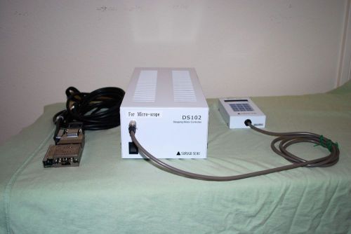
Suruga Seiki DS102 Stepping Motor Controller, DT100 Handy Terminal, PG413-R05AG
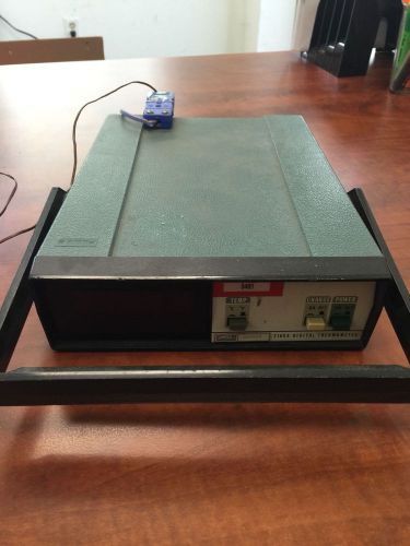
Fluke Model 2165A Digital Thermometer
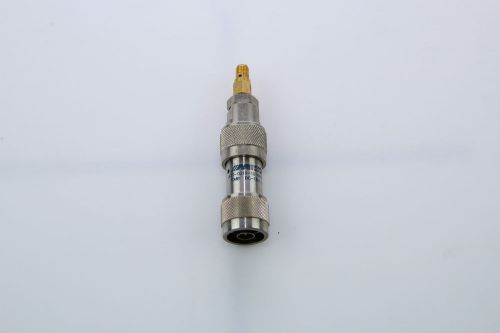
MIDWEST ATT-0219-10-NNN-02 ATTENUATOR N 18GHZ 50OHM 10DB WITH ADAPTER
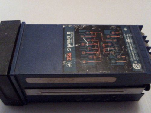
ATC 356A350Q30PX SERIES 356 SHAWNEE II COUNTER
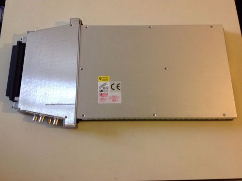
ASCOR's Model 3000-3 single- slot
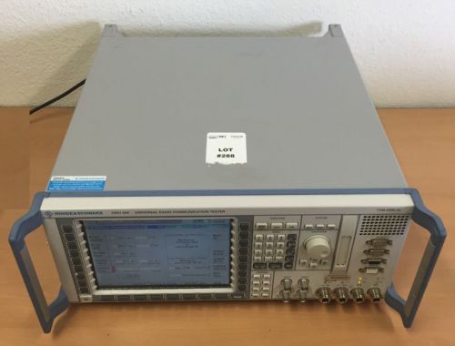
Rohde Schwarz CMU 200 Universal Radio Communication Tester Equipment
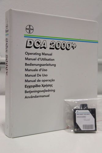
Bayer DCA 2000+ Hemoglobin A1c Analyzer Operating Manual
Rare Military WW11 Espey Vacuum Electron Tube Tester Signal Corps. stamped I-177
Tektronix 2467B 4-Channel 400MHz High Writing Speed Oscilloscope
OTC 3450 HIGH IMPEDANCE DIGITAL MULTI METER 1000V DC 150V AC VERY CLEAN
Msa Water Stop Sample Probe With Tube Connect P/N 10105839
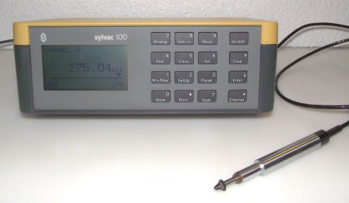
Dreher Sylvac 100 with Probe 10-14318 & Adapter - Warranty
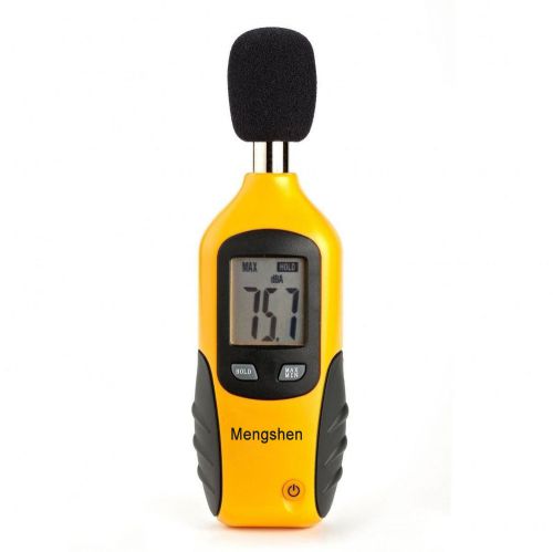
Digital Decibel Sound Meter Level Tester Pressure Noise Measurement 40-130 dBA
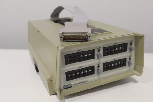
Fluke Y2002 Accessory Connector for Y2000 Y2001 Alarms Output + Free Shipping!!!
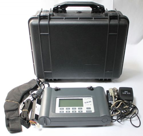
Berkeley Nucleonics Corp BNC Model SAM 935 1B Portable Gamma Spectroscopy System
HP / AGILENT 8120-2703 5' Viking to Viking Drive Cable ~ 11713A Attenuator
By clicking "Accept All Cookies", you agree to the storing of cookies on your device to enhance site navigation, analyze site usage, and assist in our marketing efforts.
Accept All Cookies