
US $130
| Condition: |
New: A brand-new, unused, unopened, undamaged item in its original packaging (where packaging is
applicable). Packaging should be the same as what is found in a retail store, unless the item is handmade or was packaged by the manufacturer in non-retail packaging, such as an unprinted box or plastic bag. See the seller's listing for full details.
...
|
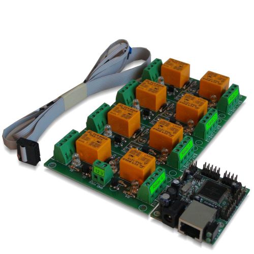
Brand | RAS-12-15 |
| Relays count | 8 | ||
| MPN | DAEnetIP2 + DAE-RB/Ro2-12V | ||
| Power supply | 12 VDC | ||
| Country of Manufacture | Bulgaria | ||
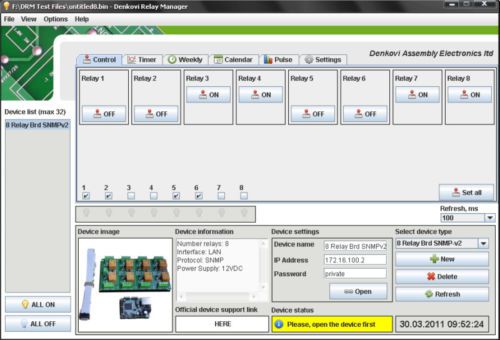
| Software | control, timer, week, calendar, schedule, pulse | ||
| Type | Relays | ||
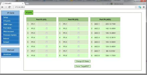
| Access way | Web, Software, Command line, SNMP | ||
| Protocol | HTTP, SNMP, ICMP, APR, TFTP |
Directions
Similar products from Relay Module Boards
Tyco (by Potter & Brumfield) high current (up to 25A) relay PRD-11DYO coil 24V
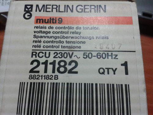
21182 - RCU VOLTAGE CONTROL RELAY 230V
1x Telewatt SU2082/36V DC - Power Relay Contactor - Three Terminal - Sweeden
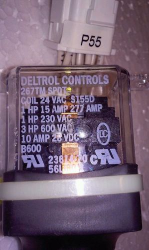
DELTROL CONTROL RELAY 267TM SPDT COIL 24VAC S155D 23614-70
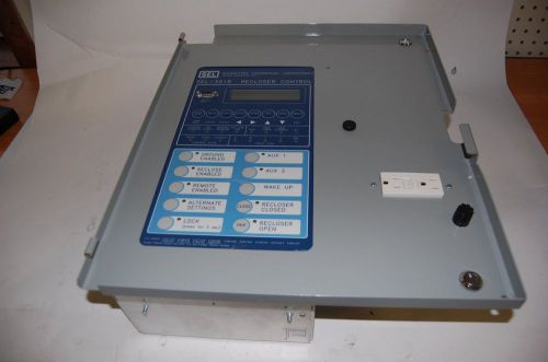
SEL 351R Rocloser Control (SCHWEITZER ENGINEERING LABORATORIES)
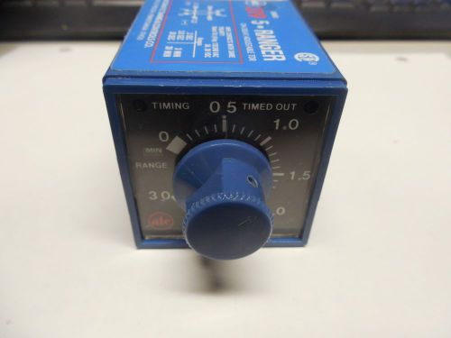
ATC ON DELAY RELAY 319D 016 Q 1C 120Vac 3 SEC.30 MIN: 8 PINS 319D016Q1C
New Struthers Dunn 120VAC Coil DPDT General Purpose Relay A311XBXP, NEW NO BOX
40441 , Siemens 3RU1126-4AB0 Overload Relay and 3RH1921-1DA11-NEMA/EEMAC Size 1
GENERAL ELECTRIC GE 17LH13D1 W/ RESISTOR ASSEMBLY RELAY D369692
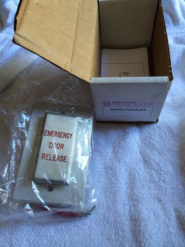
W5286-P23DAXE5 DORTRONICS DELAY 2-60 SEC EMERGENCY DOOR RELEASE / RED LETTER
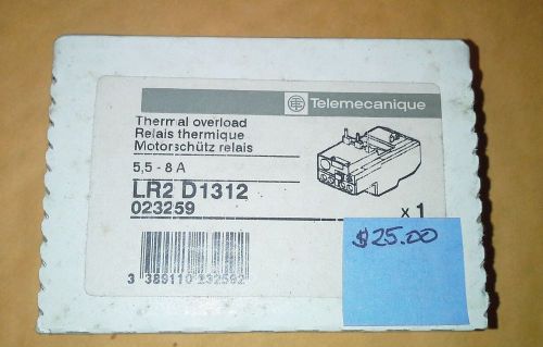
Telemecanique Thermal OverloadLR2D1312
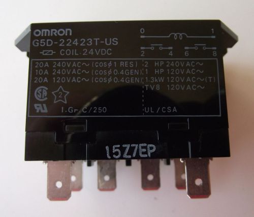
Omron relay P/N G5D-22423T-US 24 VDC Coil 120/240VAC 2NO Contacts NEW
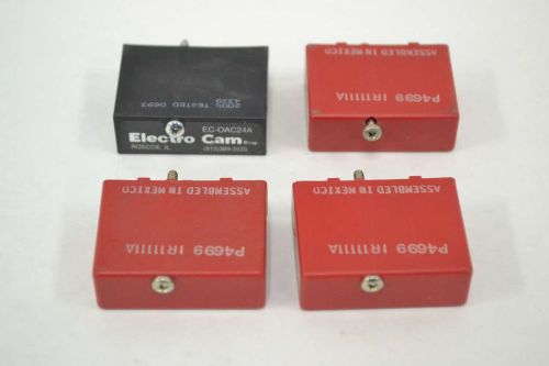
LOT 4 POTTER BRUMFIELD ASSORTED SOLID STATE RELAY ODC-24 EC-OAC24A B368098
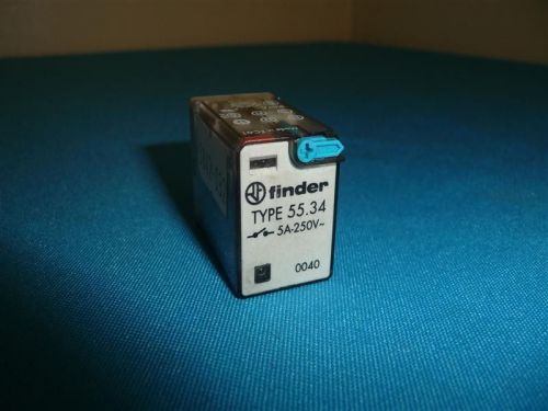
Finder Type 55.34 General Purpose Relay 5A 250V
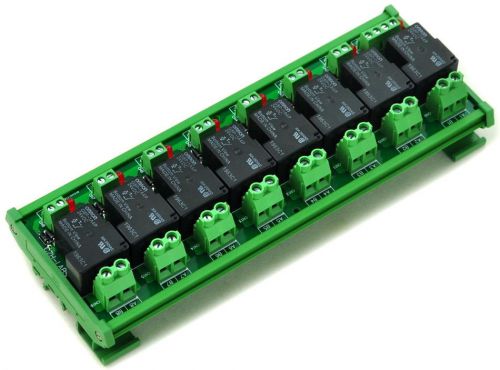
DIN Rail Mount Coil 24V Passive 8 Channel SPST-NO 30A 30Amp Power Relay Module.
Fuji Electric HH54 P-L HH54PL Relay DC 24V
Macromatic SS-60228 SS60228 Time Delay Relay
Finder Type 55.34 Relay w/ 94.74 Socket
Lot 6pcs Nais HE1aN-DC 12V AHE1211 Power Relay Defective
People who viewed this item also vieved
INTERMATIC T103 Timer, 120 Volt 24 Hour Clock, DPST
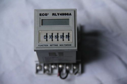
PHILIPS ECG RLY4996A PROGRAMMABLE MULTIFUNCTION DELAY RELAY 0.1S-10H TIMER
6 USED EAGLE SIGNAL ELECTRIC 30 MINUTE RACK TIMERS Ab47a6

NEW PARAGON EC7000/208-240 ELECTRONIC Time Control Programmable 24hr/7day NEW
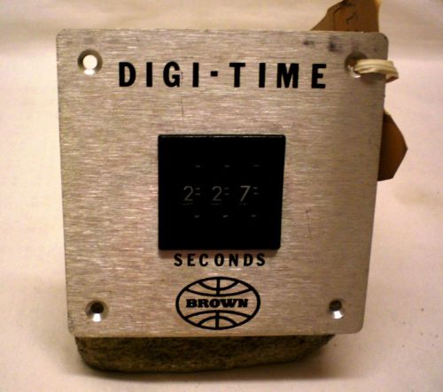
BROWN DIGI-TIME, Digital Timer, 120V AC, 1 Second - 299 Seconds
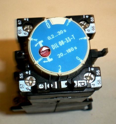
German Klockner Moeller Industrial Timer, DIN Rail Mounting, Model DIL 08-33-T
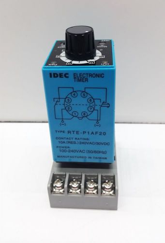
IDEC Electronic Multifunction Timer RTE-P1AF20 100-240VAC with Base 8 Pin
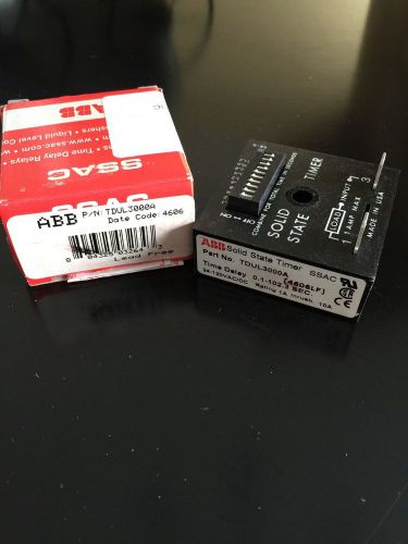
ABB TDUL3000A Solid State Timer SSAC
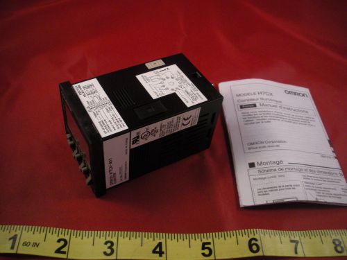
Omron H7CX-A11 Digital Counter Relay SPDT 100-240v ac lcd 11-pin Nnb New
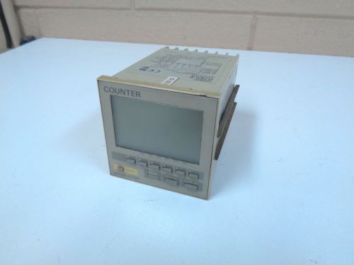
OMRON H7BR-B 100-240VAC DIGITAL COUNTER - FREE SHIPPING!!!
Eaton 5883-1 Programmable Counter
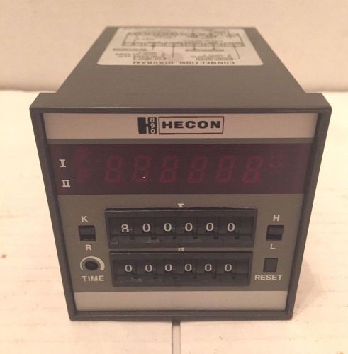
Hecon Electronic Digital Counter 0718-100
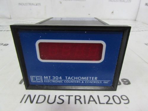
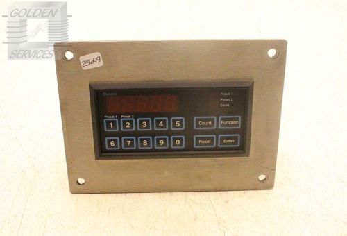
ELECTRIC COUNTERS & CONTROLS MT304A NEW
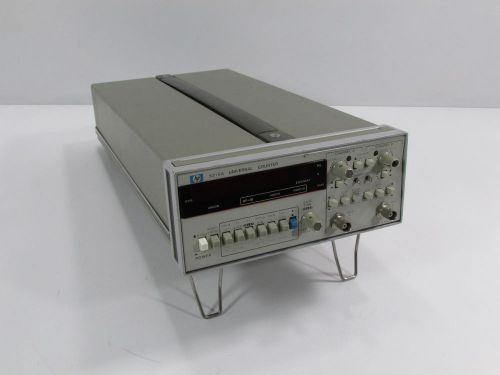
HEWLETT PACKARD HP5316A UNIVERSAL COUNTER
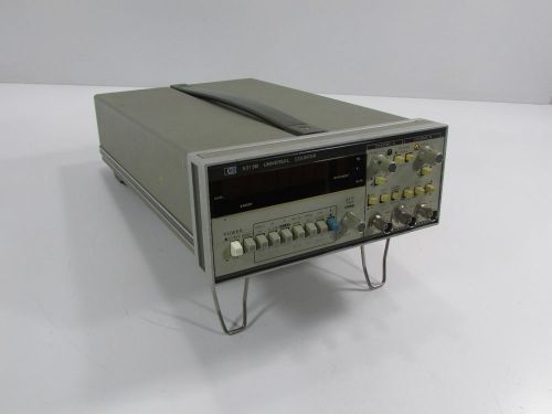
HEWLETT PACKARD HP5315B UNIVERSAL COUNTER
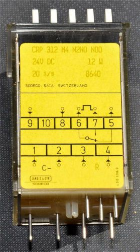
Sodeco, Landis & Gyr Counter CRP 312 M4 N2N0 N00 --New old Stock--24V DC
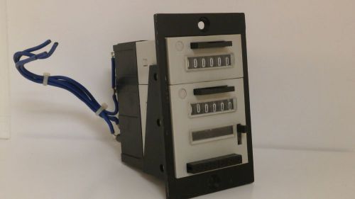
IVO 6 DIGIT DOUBLE STACKED COUNTER
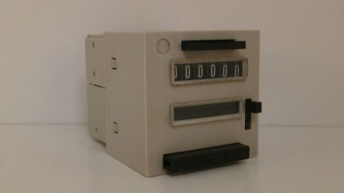
IVO 6 DIGIT COUNTER W/MANUAL RESET FE 504
By clicking "Accept All Cookies", you agree to the storing of cookies on your device to enhance site navigation, analyze site usage, and assist in our marketing efforts.
Accept All Cookies