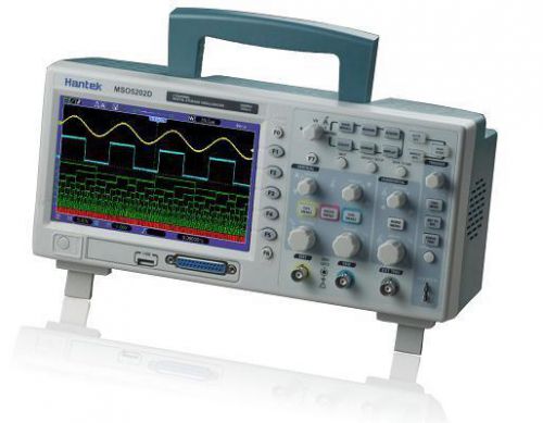
1.Feature 16 channels logic analyzer + 2 channels oscilloscope + external trigger. Big and clear display (7.0-inch color LCD, high revolution 800 x 480), clear lifelike waveform display. 1GSa/s real time sampling rate. USB host, support flash memory card storage and USB interface system upgrade. Ultrathin design, handy volume, easily portable. VGA Optional Oscilloscope Function Bandwidth 200MHz. Each channel record length up to 1M. Real time sampling rate up to 1GSa/s. Powerful trigger function. 32 kinds of automatic measurement function. Logic Analyzer Function 16 channels divided into 2 groups which is able to setup threshold level individually. Real time sampling rate up to 500MSa/s. Powerful trigger function: edge, duration, pulse width, code-type, queen, repeat. 2. Specification Model MSO5202D Acquisition Sample Rate Real-Time Sample: 1GS/s Acquisition Modes Normal Normal data only Peak Detect High-frequency and randon glith capture Average Wavefom Average, selectable 4,8,16,32,64,128 Inputs Inputs Coupling AC, DC, GND Inputs Impendance 1M?±2% ?20pF±3pF Probe Attenuation 1X, 10X Supported Probe Attenuation Factor 1X, 10X, 100X, 1000X Maximum Input Voltage CAT I and CAT II: 300VRMS (10x), Installation Category; CAT III: 150VRMS (1x); Installation Category II: derate at 20dB/decade above 100kHz to 13V peak AC at 3MHz* and above. For non-sinusoidal waveforms, peak value must be less than 450V. Excursion above 300V should be of less than 100ms duration. RMS signal level including all DC components removed through AC coupling must be limited to 300V. If these values are exceeded, damage to the oscilloscope may occur. Horizontal System Sample Rate Range 500MS/s--1GS/s Waveform Interpolation (sin x)/x Record Length 1M SEC/DIV Range 2ns/div to 40s/div, in a 2, 4, 8 sequence, Sample Rate and Delay Time Accuracy ±50ppm(at over any >=1ms time interval) Position Range 2ns/div to 10ns/div; (-4div x s/div) to 20ms; Delta Time Measurement Accuracy (Full Bandwidth) Single-shot, Normal mode:± (1 sample interval +100ppm x reading + 0.6ns); >16 averages:± (1 sample interval + 100ppm x reading + 0.4ns); Sample interval = s/div ? 200 Vertical System Vertical Resolution 8-bit resolution, all channel sampled simultaneously Position Range 2mV/div to 10V/div Bandwidth 200MHz Rise Time at BNC( typical) 1.8ns Analog Bandwidth in Normal and Average modes at BNC or with probe, DC Coupled 2mV/div to 20mV/div, ±400mV; 50mV/div to 200mV/div, ±2V 500mV/div to 2V/div, ±40V; 5V/div, ±50V Math +, -, *, /, FFT FFT Windows:Hanning,Flatop, Rectamgular,Bartlett,Blackman; 1024 sample point Bandwidth Limit 20MHz Low Frequency Response (-3db) =16:± (3% x reading + 0.1div + 1mV) only 10mV/div or greater is selected; When vertical displacement is not zero, and N>=16: ± [3% x (reading + vertical position) + 1% of vertical position + 0.2div]; Add 2mV for settings from 2mV/div to 200mV/div; add 50mV for settings from 200mV/div to 10V/div Volts Measurement Repeatability, Average Acquisition Mode Delta volts between any two averages of >=16 waveforms acquired under same setup and ambient conditions Trigger System Trigger Types Edge, Video, Pulse, Slope, Over time, Alternative Trigger Source CH1, CH2, EXT, EXT/5, AC Line Trigger Modes Auto, Normal, Single Coupling Type DC, AC, Noise Reject, HF Reject, LF Reject Trigger Sensitivity (Edge Trigger Type) DC(CH1,CH2): 1div from DC to 10MHz;1.5div from 10MHz to 100MHz; 2div from 100MHz to Full; DC(EXT): 200mV from DC to 100MHz; 350mV from 100MHz to 200MHz; DC(EXT/5): 1V from DC to 100MHz;1.75V from 100MHz to 200MHz; AC: Attenuates signals below 10Hz; HF Reject: Attenuates signals above 80kHz; LF Reject: Same as the DC-coupled limits for frequencies above 150kHz; attenuates signals below 150kHz Trigger Level Range CH1/CH2: ±8 divisions from center of screen; EXT: ±1.2V; EXT/5:±6V Trigger Level Accuracy( typical)Accuracy is for signals having rise and fall times >=20ns CH1/CH2: 0.2div x volts/div within ±4 divisions from center of screen; EXT: ± (6% of setting + 40mV); EXT/5: ± (6% of setting + 200mV); Set Level to 50%(typical) Operates with input signals >=50Hz Video Trigger Video Trigger Type CH1, CH2: Peak-to-peak amplitude of 2 divisions; EXT: 400mV; EXT/5: 2V Signal Formats and Field Rates, Video Trigger Type Supports NTSC, PAL and SECAM broadcast systems for any field or any line Holdoff Range 100ns ~ 10s Pulse Width Trigger Pulse Width Trigger Mode Trigger when (< , >, = , or ?); Positive pulse or Negative pulse Pulse Width Trigger Point Equal: The oscilloscope triggers when the trailing edge of the pulse crosses the trigger level. Not Equal: If the pulse is narrower than the specified width, the trigger point is the trailing edge. Otherwise, the oscilloscope triggers when a pulse continues longer than the time specified as the Pulse Width. Less than: The trigger point is the trailing edge. Greater than (also called overtime trigger): The oscilloscope triggers when a pulse continues longer than the time specified as the Pulse Width Pulse Width Range 20ns ~ 10s Slope Trigger Slope Trigger Mode Trigger when (< , > , = , or ? ); Positive slope or Negative slope Slope Trigger Point Equal: The oscilloscope triggers when the waveform slope is equal to the set slope. Not Equal: The oscilloscope triggers when the waveform slope is not equal to the set slope. Less than: The oscilloscope triggers when the waveform slope is less than the set slope. Greater than: The oscilloscope triggers when the waveform slope is greater than the set slope. Time Range 20ns ~ 10s Overtime Trigger Over Time Mode Rising edge or Falling edge Time Range 20ns ~ 10s Alternative Trigger Trigger on CH1 Internal Trigger: Edge, Pulse Width, Video, Slope Trigger on CH2 Internal Trigger: Edge, Pulse Width, Video, Slope Trigger Frequency Counter Readout Resolution 6 digits Accuracy (typical) ±30ppm (including all frequency reference errors and ±1 count errors) Frequency Range AC coupled, from 4Hz minimum to rated bandwidth Signal Source Pulse Width or Edge Trigger modes: all available trigger sources The Frequency Counter measures trigger source at all times, including when the oscilloscope acquisition pauses due to changes in the run status, or acquisition of a single shot event has completed. Pulse Width Trigger mode: The oscilloscope counts pulses of significant magnitude inside the 1s measurement window that qualify as triggerable events, such as narrow pulses in a PWM pulse train if set to < mode and the width is set to a relatively small time. Edge Trigger mode: The oscilloscope counts all edges of sufficient magnitude and correct polarity. Video Trigger mode: The Frequency Counter does not work. Measurement Cursor Measurement Voltage difference between cursors: ?V Time difference between cursors: ?T Reciprocal of ?T in Hertz (1/?T) Auto Measuerment Frequency, Period, Mean, Pk-Pk, Cycli RMS, Minimum, Maximum, Rise time, Fall Time, +Pulse Width, -Pulse Width, Delay1-2Rise, Delay1-2Fall, +Duty, -Duty, Vbase, Vtop, Vmid, Vamp, Overshoot, Preshoot, Preiod Mean, Preiod RMS, FOVShoot, RPREShoot, BWIDTH, FRF, FFR, LRR, LRF, LFR, LFF Logic Analyzer Specifications Channels 16 Channels Max. Input Impendence 200K(C=10p) Input Voltage Range -60V~60V Logic Threshold Range -8V~8V Max. Sample Rate 500MHz Compatible Input TTL, CMOS, ECL Sample Depth 512K Trigger Edge Trigger D0-D15 select slope (rising or falling edge) Pulse Width D0-D15 select pulse polarity (positive or negative pulse), trigger when (=, ?, >, <), trigger pulse width Code-type D0-D15 select code-type (H, L, X) Duration D0-D15 select persist time and trigger when (data terminate, data start, and data delay) Queue D0-D15 select specific data index (0-3) and code-type (H, L, X) Repeat D0-D15 select code-type (H, L, X) and repeat times General Features Display Display Type 7 inch 64K color TFT (diagonal liquid crystal) Display Resolution 800 horizontal by 480 vertical pixels Display Contrast Adjustable (16 gears) with the progress bar Probe Compensator Output Output Voltage( typical) About 5Vpp into >=1M? load Frequency(typical) 1kHz Power Supply Supply Voltage 100-120VACRMS(±10%), 45Hz to 440Hz, CATII 120-240VACRMS(±10%), 45Hz to 66Hz, CATII Power Consumption <30W Fuse 2A, T rating, 250V Environmental Temperature Operating: 32°F to 122°F (0°C to 50°C); Nonoperating: -40°F to 159.8°F (-40°C to +71°C) Cooling Method Convection Humidity +104°F or below (+40°C or below):
By clicking "Accept All Cookies", you agree to the storing of cookies on your device to enhance site navigation, analyze site usage, and assist in our marketing efforts.